ELECTRONIC SHIFT LEVER SYSTEM DETAILS
-
FUNCTION OF MAIN COMPONENTS
-
The main components of the electronic shift lever system have the following functions:
Component Function Shift Lock Control Unit Assembly Shift Lever Position Sensor Detects the shift lever position (R, N, D and B), and transmits the shift lever position to the power management control ECU (HV CPU). P Position Switch As this switch turns on, it detects the driver's intention to operate the parking lock, and sends it to the power management control ECU (HV CPU). P Position Indicator Light
-
Comes on when the parking lock is engaged and comes off when the parking lock is disengaged.
-
Blinks to alert the driver (or turns off) when the transmission control ECU detects a malfunction in the electronic shift lever system.
Parking Lock Actuator Engages or disengages the transaxle parking lock mechanism. Power Management Control ECU (HV CPU) Controls MG1, MG2 and the engine in accordance with each shift position, based on signals from the shift lever position sensor, P position switch and various ECUs. In addition, it sends the parking lock or unlock request signal to the transmission control ECU. Transmission Control ECU
-
Drives the parking lock actuator in accordance with the parking lock or unlock request signal from the power management control ECU (HV CPU).
-
Receives the gearshift control lock/unlock signal from the immobiliser code ECU, and activates/deactivates the gearshift control lock.
Certification ECU Verifies the ID code output from the key. Immobiliser Code ECU Compares the ID code. Combination Meter Assembly Shift Position Indicator Illuminates the shift position indicator, which the driver has selected, in accordance with the shift position signals from the power management control ECU (HV CPU). Buzzer Sounds to alert the driver when the reject function is activated. Multi-information Display
-
Displays a warning message to alert the driver in accordance with a signal provided by the power management control ECU (HV CPU) and transmission control ECU.
-
The master warning light may illuminate depending on the message displayed on the multi-information display.
-
-
-
SYSTEM CONTROL
-
Shift Control
-
The power management control ECU (HV CPU) controls MG1, MG2 and the engine according to the shift position (R, N, D and B) that determined using signals from the shift lever position sensor and the switch on signal from the P position switch. In addition, the power management control ECU (HV CPU) sends a parking lock or unlock request signal to the transmission control ECU.
-
The transmission control ECU drives the parking lock actuator based on the parking lock or unlock request signal from the power management control ECU (HV CPU) to engage or disengage the parking lock mechanism. In addition, it sends the parking shift position signal to the power management control ECU (HV CPU).
-
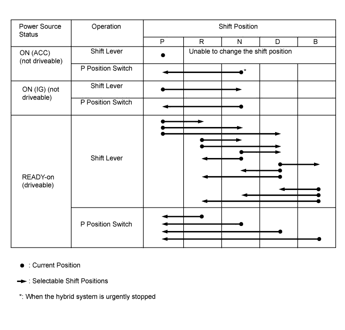
When the vehicle is being driven under normal conditions, the shift position can be changed to all positions, provided that the reject function has not been tripped.
-
When the power switch is turned off with the vehicle stopped, the shift position is automatically changed to P.
-
The table below shows the shift position that results from shift lever and P position switch operation according to the power source status.
-
-
-
FUNCTION
-
Reject Function
-
To ensure safety, this system might not change the shift position even if the driver operates the shift lever or P position switch. In that case, it sounds a reject buzzer and changes the shift position as shown in the following table.
Shift operation which causes reject function to operate Shift position after rejection Without depressing the brake pedal and with park (P) selected, the driver moves the shift lever to select another lever position. Held in P position While driving, the driver pushes the P position switch. Changed to N position While driving, the driver moves the shift lever to R when drive (D) has been selected, or to D when reverse (R) was previously selected. Changed to N position The driver moves the shift lever to B when park (P) was previously selected. Held in P position The driver moves the shift lever to B when reverse (R) was previously selected. Changed to N position The driver moves the shift lever to B when nuetral (N) was previously selected. Held in N position
-
-
Shift Position Indicator
-
The shift lever is designed to always return to its home position. Therefore, the shift position that is currently selected can be checked on the shift position indicator, which is provided in the combination meter assembly.
-
In this system, B provides engine braking. Therefore, changing to B from a position other than D is prohibited. Accordingly, if the shift position is other than D or B, the B position indicator will turn off to prevent the driver from inadvertently moving the shift lever to B.
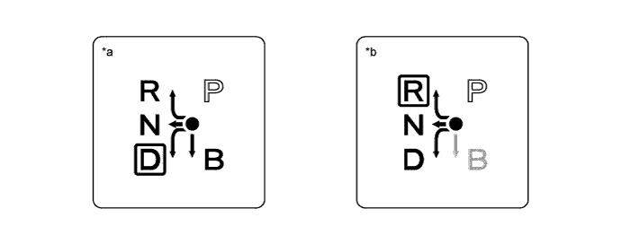
Text in Illustration *a Displayed when the shift position is in D. *b Displayed when the shift position is in R.
-
-
-
CONSTRUCTION
-
Shift Lock Control Unit Assembly
-
The shift lock control unit assembly is a momentary shift type in which the reactive force of a spring returns the lever to its home position when the driver's hand is released from a shift lever after a shifting operation.
-
The shift lock control unit assembly has a built-in shift lever position sensor consisting of a select sensor and shift sensor to detect the shift lever position (R, N, D and B).
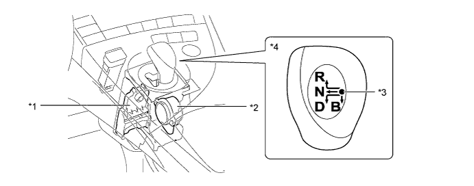
Text in Illustration *1 Select Sensor *2 Shift Sensor *3 Home Position *4 Shift Knob
-
-
Shift Lever Position Sensor
-
The shift lever position sensor for detecting the R, N, D or B shift lever position is built into the shift lock control unit assembly.
-
The shift lever position sensor consists of a select sensor that detects the lateral movement of the shift lever, and a shift sensor that detects the longitudinal movement of the shift lever.
-
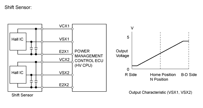
The select sensor and the shift sensor use Hall ICs for position detection.
-
The select sensor and shift sensor Hall ICs each contain 2 circuits, one for the main signal, and one for the sub signal. The Hall ICs convert the shift position into electric signals that have differing characteristics and outputs them to the power management control ECU (HV CPU).

Text in Illustration *1 Select Sensor *2 Shift Sensor *3 Magnet Slider *4 Hall IC *5 Magnet Yoke - - 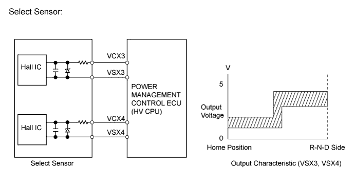
-
The power management control ECU (HV CPU) selects the shift position in accordance with the combination of signals from the select sensor and the shift sensor as shown in the following table.
Selected Shift Position Select Sensor Detection Position
(Lateral Movement)
Shift Sensor Detection Position
(Longitudinal Movement)
R R-N-D Side R Side N R-N-D Side Home Position D R-N-D Side B-D Side B Home Position B-D Side
-
-
Parking Lock Actuator
-
The parking lock actuator consists of a switched reluctance motor and a cycloid reduction mechanism.
-
The parking lock actuator is mounted on the side of the transaxle. Upon receiving an actuation signal from the transmission control ECU, the motor rotates to engage or disengage the parking lock mechanism. As a result, the transaxle is locked or unlocked mechanically.
-
The switched reluctance motor is mainly composed of coil, stator, rotor and rotation angle sensor, and brushes and magnets are not used.
-
The rotation angle sensor consists of 2 Hall ICs. The 2 of them, called phases A and B, are used to detect the rotation angle of motor.
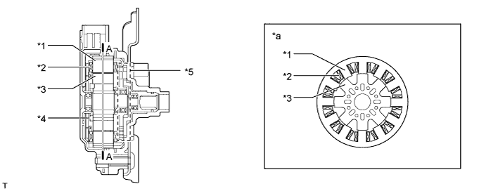
Text in Illustration *1 Stator *2 Coil *3 Rotor *4 Rotation Angle Sensor *5 Cycloid Reduction Mechanism - - *a A-A Cross Section - - -
This motor rotates to lock or unlock parking. The transmission control ECU detects the present shift position (Parking locked or unlocked) in accordance with the rotation angle signal, which detects the extent of rotation of the motor.
-
The transmission control ECU detects the direction of the motor rotation, the extent of the rotation, and its moving range through the combination of the pulses and the counting of the 2 Hall ICs with staggered phases (A phase and B phase), which are located in the rotation angle sensor. Once the moving range is detected, it is stored in the transmission control ECU memory. However, it will be deleted if a battery terminal is disconnected.
Count Timing Pulse Changes A Phase B Phase Lock → Unlock OFF → OFF OFF → ON OFF → ON ON → ON ON → ON ON → OFF ON → OFF OFF → OFF Unlock → Lock OFF → ON OFF → OFF OFF → OFF ON → OFF ON → ON OFF → ON ON → OFF ON → ON 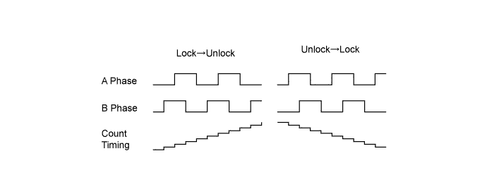
-
The parking lock position and unlock position, which provide the values to establish control criteria, are detected and stored in memory at the time the transmission control ECU is started or the battery is reconnected. Initially, the transmission control ECU causes the motor to rotate to the position that engages the lock, in order to store the parking lock position in memory. Then, the transmission control ECU causes the motor to rotate in reverse, in order to store the unlock position in memory. However, if the transmission control ECU has stored the moving range of the previous operation in its memory, it detects one of the present positions, and calculates the other position from the moving range stored in memory. These processes make it unnecessary for the system to be initialized after the actuator or the transmission control ECU is replaced or the battery terminal is reconnected.
-
The cycloid reduction mechanism ensures the complete releasing operation for the parking lock when the vehicle is parked on a sloping road in which requires a high torque, since it amplifies the torque of the motor output shaft.
-
This mechanism consists of an eccentric plate that is mounted on the motor output shaft, an inside gear (61 teeth) that is secured to the housing, an outside gear (60 teeth), and an output shaft that rotates in unison with the outside gear.
-
Along with the rotational movement of the eccentric plate, which rotates in unison with the motor output shaft, the inside gear pushes against the outside gear, while meshing. The outside gear, which has 1 tooth less than the inside gear, rotates 1 tooth less per rotation of the eccentric plate. As a result, the output shaft, which rotates in unison with the outside gear, outputs the rotational movement of the motor at a reduction ratio of 61.
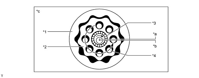
Text in Illustration *1 Inside Gear *2 Outside Gear *3 Eccentric Plate *4 Output Shaft *a Eccentric Plate Center *b Motor Input Shaft Center *c Image of Cycloid Reduction Mechanism - - 
Rotation Direction - -
-
-
Parking Lock Mechanism
-
The parking lock mechanism consists of a parking lock lever, parking lock rod, parking lock pawl and parking gear.
-
The engagement of the parking lock pawl with the parking gear that is integrated with the compound gear locks the movement of the vehicle.
-
The parking lock actuator rotates the parking lock lever to slide the parking lock rod, which pushes up the parking lock pawl. As a result, the parking lock pawl engages with the parking gear.
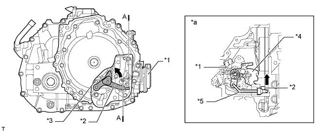
Text in Illustration *1 Parking Lock Actuator *2 Parking Lock Pawl *3 Parking Gear *4 Parking Lock Lever *5 Parking Lock Rod - - *a A-A Cross Section - - Movement - -
-
-
-
FAIL-SAFE
-
If the transmission control ECU detects a malfunction in the system, the transmission control ECU controls the system according to the data already stored in memory. For details, refer to the Repair Manual.
-
-
DIAGNOSIS
-
If the transmission control ECU detects a malfunction in the electronic shift lever system, the transmission control ECU blinks the P position indicator light, illuminates the master warning light and displays a message "P LOCK MALFUNCTION WHEN PARKING, PARK IN FLAT PLACE AND APPLY PARKING BRAKE SECURELY" on the multi-information display to inform the driver. If the power management control ECU (HV CPU) detects a malfunction in the electric shift lever system, it also illuminates the master warning lights and displays the message "CHECK HYBRID SYSTEM" on the multi-information display.
-
When the transmission control ECU or power management control ECU (HV CPU) detects a malfunction in the electronic shift lever system, the transmission control ECU or power management control ECU (HV CPU) performs a diagnosis and memorizes the failed section. At the same time, the Diagnostic Trouble Code (DTC) is stored in its memory.
-
The DTC can be read by connecting the Intelligent Tester to the DLC3. For details, refer to the Repair Manual.
-