FUEL SYSTEM DETAILS
-
CONSTRUCTION
-
Fuel Delivery Pipe
-
A pressed steel fuel delivery pipe is used.
-
Pulsation that occurs when the fuel is fed is absorbed by the volume change caused by bending in the fuel delivery pipe sub-assembly. Therefore, the separately provided pulsation damper has been discontinued, reducing the size and weight.
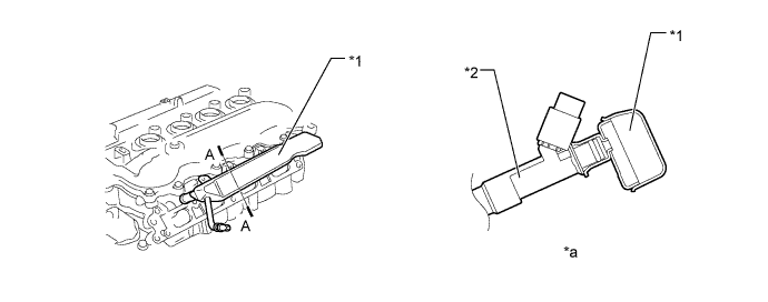
Text in Illustration *1 Fuel Delivery Pipe *2 Fuel Injector *a A-A Cross Section - -
-
-
Fuel Injector
-
The injector is shaped from a long nozzle. This shortens the distance from the injector to intake valve, which prevents the fuel from adhering to the intake port walls and reduces exhaust emissions.
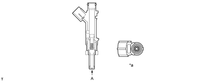
Text in Illustration *a View from A - -
-
-
Fuel Tank Assembly
-
A multiplex layered plastic fuel tank is used. This fuel tank consists of 6 layers of 4 types of materials.
-
The fuel tank assembly has been placed in the center of the vehicle (rear seat foot area) to shorten the vehicle overall length, furthermore, the fuel pump module component parts have been separated into the main and sub modules to reduce the fuel tank assembly height to 110mm (4.3 in.), providing foot room for rear passengers.
-
The top and back faces of the fuel tank assembly have been unified partially, enhancing the rigidity of the fuel tank assembly.
-
A drain mark has been provided at the lowest position of the fuel tank. When dismantling (scrapping) the vehicle, drain fuel by drilling a hole at the drain mark.
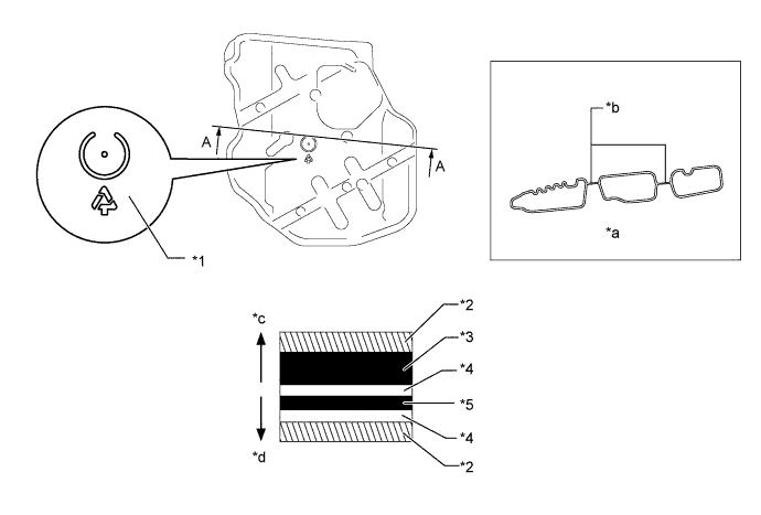
Text in Illustration *1 Drain Mark *2 HDPE (High Density Polyethylene) *3 Regrind Material *4 Adhesive *5 EVOH (Ethylene Vinyl Alcohol Copolymer) - - *a A-A Cross Section *b Unified *c Fuel Tank Outside *d Fuel Tank Inside -
A camlock mechanism is used to couple the main and sub modules of the fuel tank assembly. Changing the conventional tightening method to the camlock method reduces the height where the modules are coupled, as a result, the overall fuel tank assembly height has been lowered.
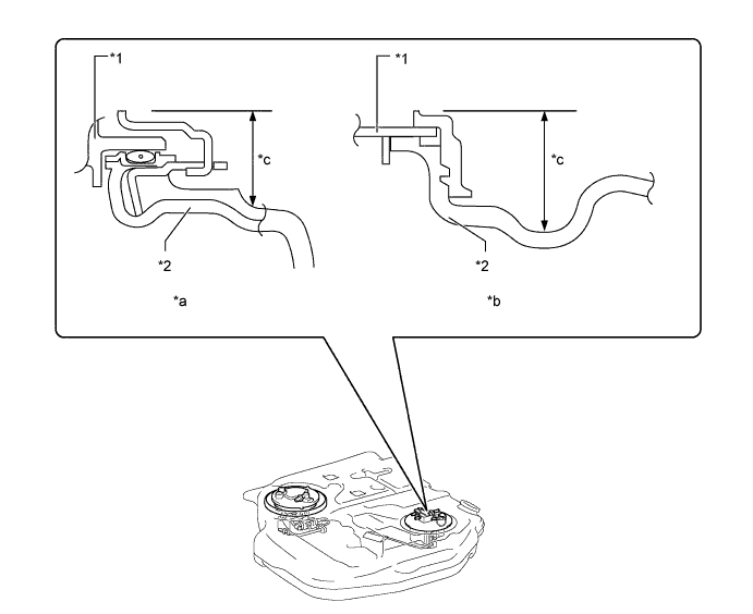
Text in Illustration *1 Module *2 Fuel Tank Assembly *a iQ *b Conventional Model *c Coupling height - -
-
-
Module Fuel Pump
-
In addition to use of a traversed-mounted fuel pump and a thin fuel filter, the component parts have been put together into the main module and sub module respectively. The main module consists of a fuel pump, a fuel filter, a suction filter, a jet pump, and a fuel pressure regulator, and the sub module consists of a fuel sender gauge, a canister, and a suction tube. This separation contributes to lower the height of the fuel pump, resulting in a reduction of the overall fuel tank height.
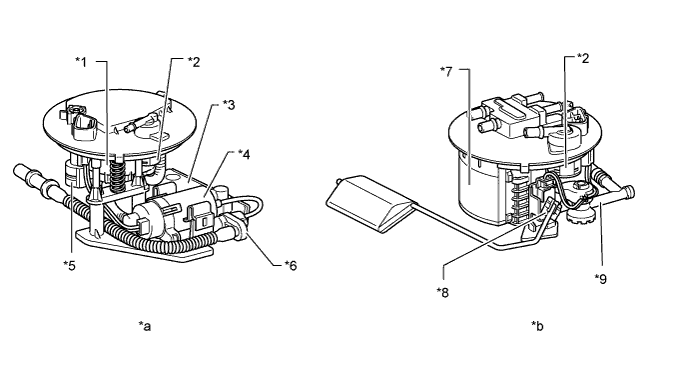
Text in Illustration *1 Fuel Filter *2 Cut Off Valve *3 Fuel Pump Filter *4 Fuel Pump *5 Fuel Pressure Regulator Assembly *6 JET Pump *7 Canister *8 Fuel Sender Gage Assembly *9 Suction Tube - - *a Main Module *b Sub Module
-
-
Canister
-
The sub module has a built-in canister to ensure an effective use of space in the engine compartment.
-
The fuel evaporative gas absorption method has been changed from the U-flow method to the W-flow method, as a result, even with the lower height, the absorbing performance equivalent to the U-flow method is achieved. In addition, the canister height has been allowed to be reduced, thus, resulting in a reduction of the overall fuel tank assembly height.
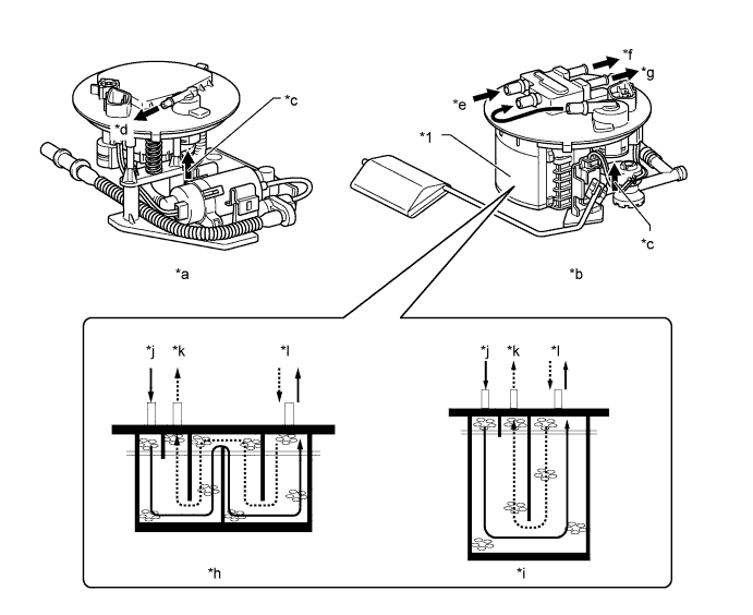
Text in Illustration *1 Canister - - *a Main Module *b Sub Module *c Fuel Evaporative Gas *d To Sub Module *e From Main Module *f Atmosphere *g To VSV (for EVAP) *h iQ *i Conventional Models *j Absorption *k Purge *l Atmospheric Air
-
-
Jet Pump
-
Since the fuel tank assembly height is low, the area of the bottom of the fuel tank assembly is larger than that of other front wheel drive vehicles in order to provide the appropriate tank capacity. Thus, due to the centrifugal force occurring in turning, the fuel height level will be slanted, this may result in running out of fuel. As this countermeasure, a jet pump is provided in the fuel tank assembly.
-
A part of the fuel pumped by the fuel pump is transferred to a jet pump and the jet pump sucks up the fuel by a negative pressure generated when the fuel passes through the orifice, transferring the fuel form the sub module to the main module, thus, preventing discontinuity of the fuel transfer adjacent to the main module even if there is any unevenness in the fuel.
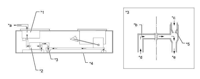
Text in Illustration *1 Fuel Filter *2 Fuel Pump *3 JET Pump *4 Fuel Tank Assembly *5 Orifice - - *a To Engine *b Fuel from Sub Module *c From Fuel Pump *d From Sub Module *e To Main Module - -
-
-