BODY STRUCTURE DETAILS
-
FUNCTION
-
Impact Absorbing Structure for Front Collisions
-
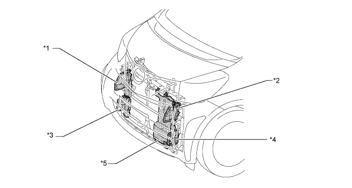
A new frame structure is used, in which load impacts in a frontal collision can be absorbed and dissipated into as many members as possible. In addition, the cabin frame has been strengthened and frames are directly joined to each other, thus minimizing the cabin deformation in the event of a collision.
-
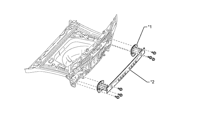
By providing a grid-like front suspension member, impact loads in the event of a collision are distributed to the front suspension member, thus reducing the loads to the front side member. In addition, the front suspension member is directly joined to the floor frame to dissipate the loads throughout the entire body frames.
-
The front tires are mounted so far forward so that impact loads in the event of a collision can be dissipated into the tires, thus reducing the load on the cabin.
-
The dash cross-member has been increased in size to dissipate impact loads into areas opposite to the collision area in the event of an offset collision.
-
The front side member and the rocker frames are directly joined to enhance the strength of the cabin.
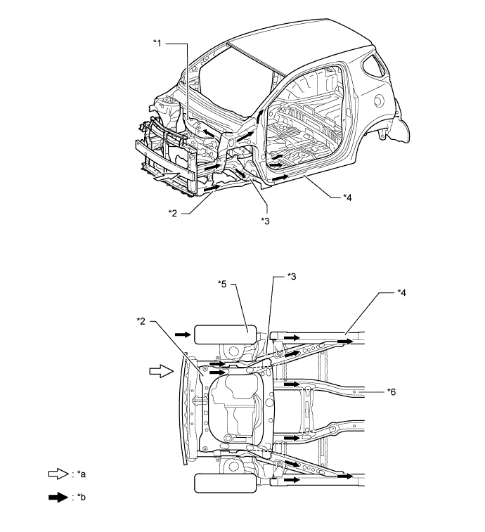
Text in Illustration *1 Dash Panel Cross Member (Front Cross Member) *2 Front Suspension Member (Front Frame Assembly) *3 Front Side Member *4 Rocker Reinforcement *5 Front Tire *6 Front Floor Reinforcement *a Impact *b Dissipate -
An impact absorbing pad with sound absorbing performance is mounted from the lower surface of the dash panel to the floor front end to reduce damage to the legs.
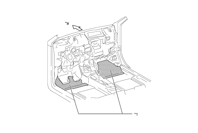
Text in Illustration *1 Impact Absorbing Pad - - *a Front - -
-
-
Impact Absorbing Structure for Side Collision
-
The impact absorbing structure is designed to dissipate impact loads throughout the entire body frame in the event of a side collision.
-
A bulkhead is used for the center pillar lower reinforcement to efficiently transmit the impact loads from the impact beam to the floor cross member.
-
A bulkhead is provided in the rocker member to reduce the cross-sectional deformation in the event of a collision.
-
Energy absorbing pads are used inside the door trims to dampen the impact energy applied to the abdomen and pelvis of the occupant in a side collision. The arm rest top face has also been made thinner to dampen the impact energy applied to the occupant.
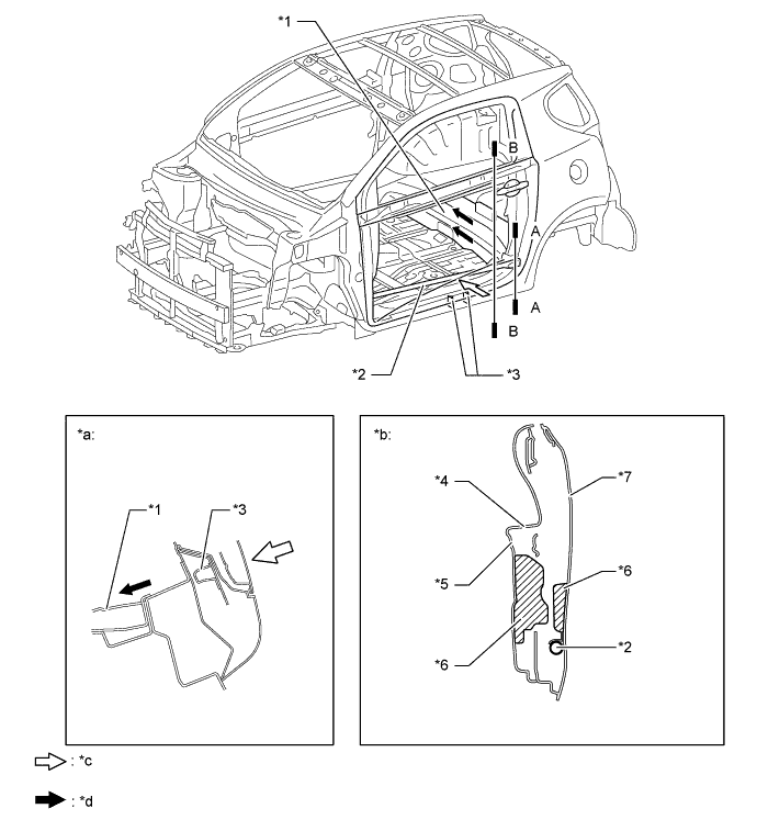
Text in Illustration *1 Rear Floor Cross Member *2 Side Impact Protection Beam *3 Bulkhead *4 Door Armrest *5 Front Door Trim Board *6 Energy Absorbing Pad *7 Front Door Panel - - *a A-A Cross Section *b B-B Cross Section *c Impact *d Dissipate -
A head impact protection structure is used. With this type of construction, if the occupant's head hits against the pillar and roof side panel due to a collision, the inner ribs of the pillar collapse to help reduce the impact.
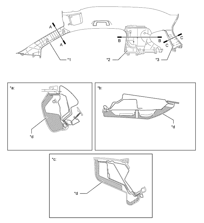
Text in Illustration *1 Front Pillar Garnish *2 Center Pillar Garnish *3 Roof Side Garnish - - *a A-A Cross Section *b B-B Cross Section *c C-C Cross Section *d Energy Absorbing Rib
-
-
Lessening Pedestrian Injury
-
The hood panel, front fender, cowl top panel and front bumper are designed to absorb impact energy to dampen the impact applied to the head and legs of a pedestrian in case of a collision.
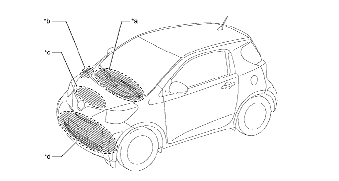
Text in Illustration *a Cowl Top Panel Area *b Front Fender Area *c Hood Panel Area *d Front Bumper Area -
A hood lock reinforcement with a pantograph cross-section is used to absorb the impact energy. In addition, the hood lock striker is arranged far away from the hood panel to ensure impact energy absorbing stroke.
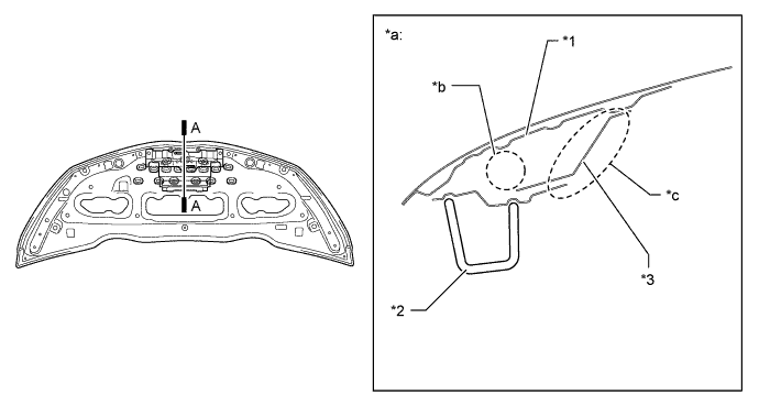
Text in Illustration *1 Hood Inner Panel *2 Hood Lock Striker *3 Hood Lock Reinforcement - - *a A-A Cross Section *b Energy Absorbing Space *c Pantograph Cross Section - - -
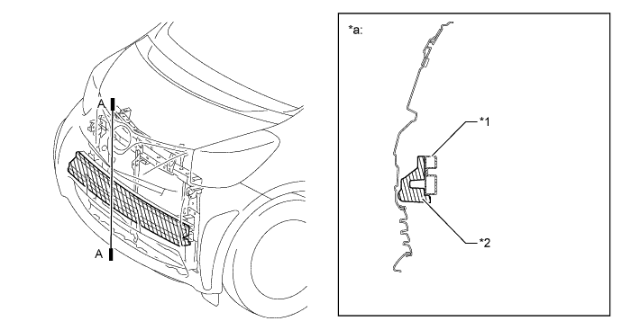
An impact absorbing bracket is used for the mounting portion of the front fender panel to absorb impact energy to the head of the pedestrian in a collision, thus dampening the impact to the head.
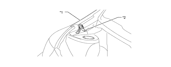
Text in Illustration *1 Front Fender Panel (Front Fender Sub-assembly RH) *2 Impact Absorbing Bracket (Fender Apron Plate) -
An open section structure is used for the cowl, which efficiently absorbs the impact energy applied from the estimated direction of a collision with the head of a pedestrian, thus reducing the injury rate. In addition, energy absorbing space is ensured between the wiper pivot and the cowl top outer front panel so that the wiper pivot can move in the event of a collision to minimize the injury.
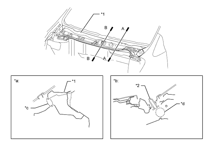
Text in Illustration *1 Cowl Top Panel *2 Wirer Pivot *a A-A Cross Section *b B-B Cross Section *c Open Section *d Energy Absorbing Space -
An energy absorber is provided at the front of the front bumper reinforcement to dampen the impact to the legs in the event of a collision with a pedestrian.
Text in Illustration *1 Front Bumper Reinforcement *2 Front Bumper Energy Absorber *a A-A Cross Section - -
-
-
Aerodynamics
-
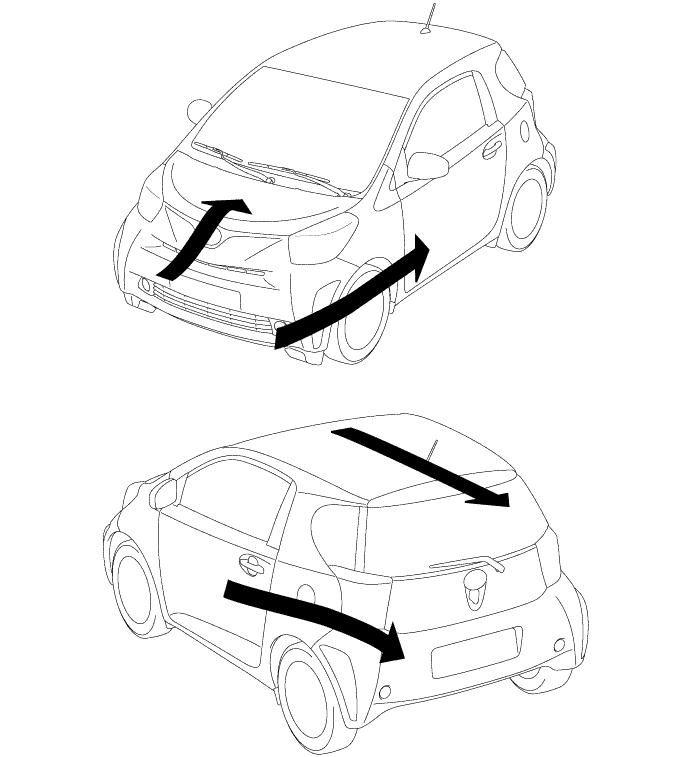
By forming a streamline from the hood through the windshield to the roof, minimizing the offset among body parts, optimizing the surface shapes and using various aero parts, excellent aerodynamic performance has been attained and high fuel economy, driving stability and straight driving stability at high speeds have also been ensured. Furthermore, these reduce wind noise, leading to an improvement in interior quietness.
-
Spats are fitted at the front of the front and rear tires to direct the air flow, and this reduces air turbulence into the wheel house, leading to good straight driving stability at high speeds.
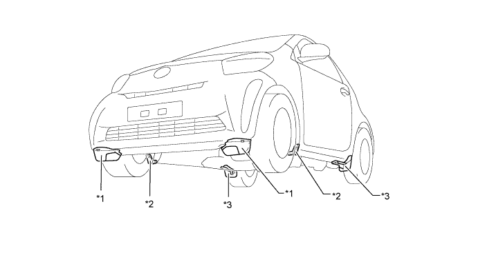
Text in Illustration *1 Spats (Front Wheel Opening Extension Pad) *2 Spats (Fender Rear Plate Mudguard) *3 Spats (Front Plate Rear Wheel House) - - -
The engine undercover and the floor undercover, which can help direct air flow under the floor, are mounted underneath the floor, and the rear floor pan is slanted upward toward the rear of the vehicle, giving excellent aerodynamic performance and ensuring a high level of driving stability and straight driving stability at high speeds.
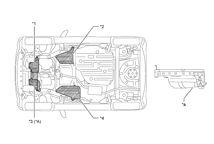
Text in Illustration *A Models with 1KR-FE Engine - - *1 No. 2 Engine Under Cover *2 Front Floor Cover LH *3 Engine Under Cover RH *4 Front Floor Cover RH *a Rear Floor Pan Slant Shape - - -
The deflector is installed onto the radiator support to direct driving airflow into the radiator, thus leading to improvement in the ventilation performance of the vehicle front section.
Text in Illustration *1 No. 1 Radiator Side Air Seal *2 No. 2 Radiator Side Air Seal *3 Radiator Support Extension RH *4 Radiator Support Extension LH *5 Radiator Lower Air Deflector - -
-
-
-
CONSTRUCTION
-
High Strength Sheet Steel
-
A highly rigid yet lightweight vehicle body has been created by considerable use of mainly high strength sheet steel for body frames, thus ensuring a high level of impact safety, driving stability and quietness.
-
An ultra high strength steel sheet is used for the front bumper reinforcement to improve the flexural resistance of the bumper reinforcement, thus ensuring the energy absorbing efficiency around the front body parts in the event of a minor collision.
Text in Illustration *a Ultra High Strength Steel Sheet *b High Strength Steel Sheet
-
-
Body Shell Construction
-
The cowl top side panel and the front pillar reinforcement are spot-welded to enhance the joint rigidity of the suspension tower and dissipate the impact to the front pillar, thus ensuring driving stability.
-
The cowl side brace is attached between the cowl top side panel and the front pillar to improve the joint rigidity between the cowl and the front pillar, and this ensures driving stability.
-
The suspension tower and the cowl are joined and the reinforcement member is optimally positioned to increase the horizontal rigidity, and this ensures driving stability.
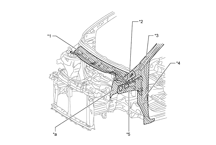
Text in Illustration *1 Cowl Top Panel *2 Cowl Side Brace *3 Front Pillar *4 Front Pillar Reinforcement *5 Cowl Top Side Panel Sub-assembly - - *a Suspension Tower - - -
By increasing the joint rigidity among the rear pillar, the lower back panel and the rear header panel, the rigidity of the back door open section has been improved, help to prevent the cabin from being deformed. In addition, the rear absorber mounting portion and the lower part of the rear pillar are effectively joined to ensure a highly rigid yet lightweight vehicle body structure and driving stability.
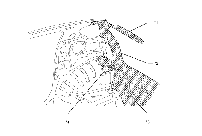
Text in Illustration *1 Rear Header Panel *2 Rear Pillar *3 Lower Back Panel (Body Lower Back Panel Sub-assembly) - - *a Rear Absorber Mounting Portion - - -
The center floor and the rear floor are joined through the rear cross member to improve the rigidity around the rear body, thus ensuring driving stability.
-
The brace is attached to the rear suspension mounting portion to improve the rigidity around the rear body, thus ensuring driving stability.
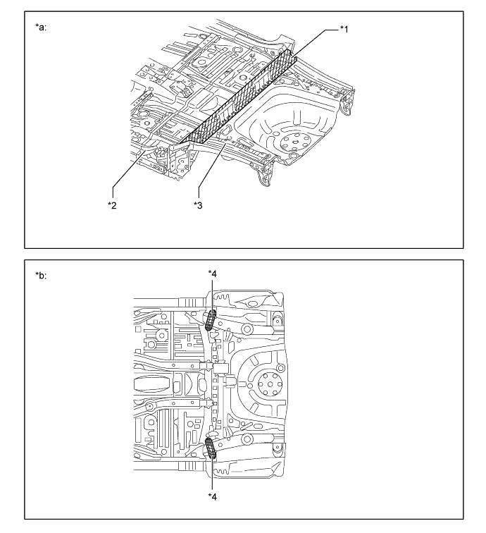
Text in Illustration *1 Rear Floor Cross Member *2 Center Floor *3 Rear Floor *4 Floor Panel Front Brace *a View from Top Side *b View from Bottom Side
-
-
Anti-corrosion Sheet Steel
-
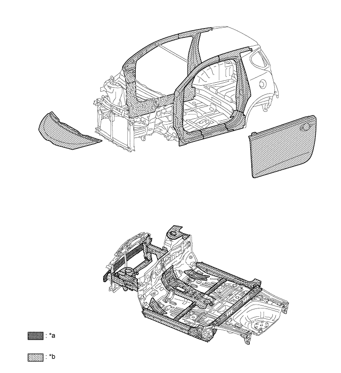
Anti-corrosion sheet steel is used as in the following illustration.

Text in Illustration *a Anti-corrosion Sheet Steel - -
-
-
Wax and Sealer
-
Wax is applied to front end of hood, edge of the front & back door lower portion, door hinge and fuel filler lid hinge to improve rust-resistant performance. Sealer is applied to hemmed portions of the front end of hood, front & back door panels and fuel filler lid.
-
-
Under Coat
-
An under coat is also applied to the under side of the body, thereby reducing splash noise and improving quietness.
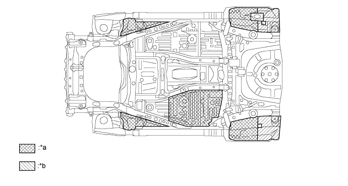
Text in Illustration *a Foamed Under Coating Area *b Foamed Under Coating Area (Thick Coating)
-
-
Anti-chipping Application
-
A PVC (Polyvinyl Chloride) chip primer is used for the rocker panel and spats are fitted to the end of the rocker panel to prevent damage from stone chipping. In addition, a soft-chip primer is used for the end of the hood.
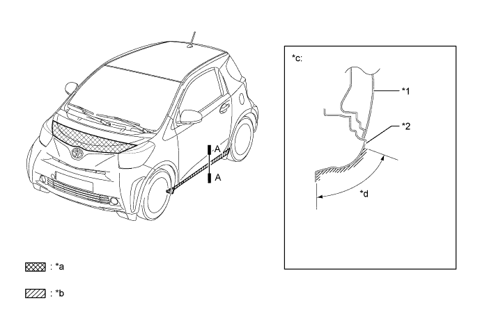
Text in Illustration *1 Door Panel *2 Rocker Panel *a Soft-chip Primer *b PVC-chip Primer *c A-A Cross Section *d PVC-chip Primer Coating Area
-
-
Sound Absorbing and Vibration Damping Materials
-
Foamed urethane sponge, foamed sealing material and sealing material are applied onto the roof panel and pillars to reduce wind and road noise.
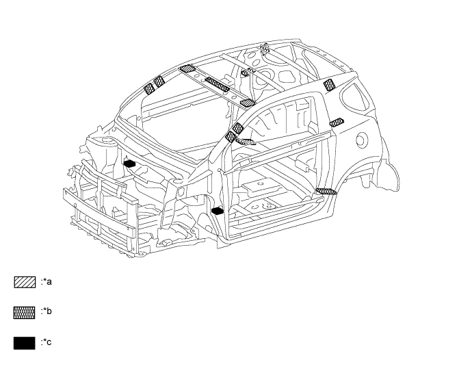
Text in Illustration *a Polyethylene Sealer *b Expanded Form *c Polyurethane Form - - -
A material having high sound-shielding property is used for the intermediate film of the laminated glass of the windshield to reduce wind noise.
-
A hood insulator is fitted to the underneath the engine hood, so that an air layer is provided between the hood panel and the insulator, forming a dual-layer structure, thus enhancing the noise-shielding performance.
-
The cowl top panel insulator is provided at the front of the cowl top panel to reduce noise from engine room.
-
The side protector is used in the front fenders to block noise and air flow from between the fender and the front pillar to the doors, thus reducing noise from the wheel house and engine room.
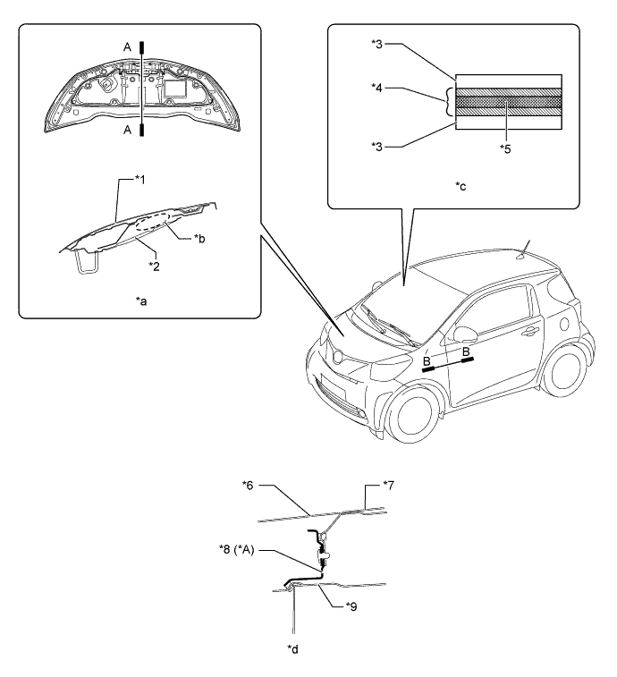
Text in Illustration *A Models with 1NR-FE Engine - - *1 Hood Panel *2 Hood Insulator *3 Glass *4 Intermediate Film *5 Sound Shielding Film *6 Front Fender Sub-assembly LH *7 Front Door *8 Front Fender Side Panel Protector LH *9 Front Pillar - - *a A-A Cross Section *b Air Layer *c Windshield Glass Cross Section *d B-B Cross Section -
The insulator is provided on both sides of the dash panel to reduce the noise being transmitted from the engine room. In addition, the dash panel insulator assembly on the cabin side includes low density absorption material for the dash panel side and high density absorption material for the cabin side, forming a dual-layer structure, thus achieving a weight reduction while ensuring sound absorption performance.
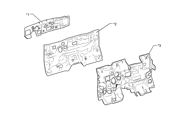
Text in Illustration *1 Outer Dash Panel Insulator *2 Dash Panel *3 Dash Panel Insulator Assembly - - -
The reinforcement is provided at the front of the floor tunnel to suppress the movement of the floor frame and reduce floor vibration. Furthermore, an asphalt sheet is effectively covered over the floor to dampen the floor vibration and reduce the road noise, thus improving quietness.
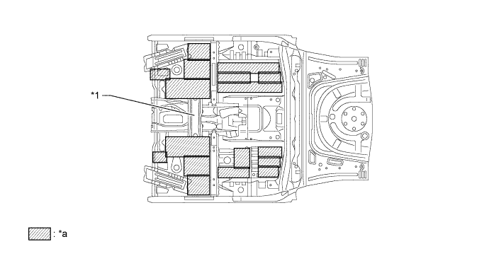
Text in Illustration *1 Reinforcement - - *a Vibration Damping Foam Coating - -
-
-
Parts with Low Repair Cost
-
A front bumper reinforcement of ultra high strength sheet steel and a high-efficiency energy absorbing bumper arm are used, which are joined to the front side member using a bolt, thus reducing collision repair cost. The radiator support components are also joined using a bolt to reduce repair cost.
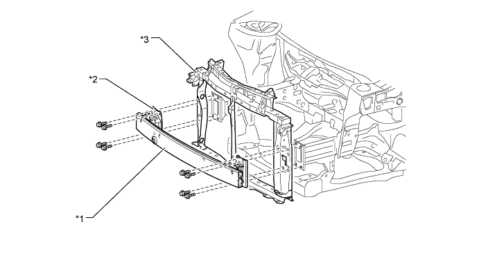
Text in Illustration *1 Front Bumper Reinforcement *2 Front bumper Arm *3 Radiator Support Assembly - - -
The rear bumper arm with a polygonal section is used to efficiently absorb energy, and is joined to the body using a bolt to reduce the repair cost in case of a minor collision. In addition, the thickness of the bumper reinforcement and the bumper arm has been optimized to achieve weight reduction.
Text in Illustration *1 Rear Bumper Arm *2 Rear Bumper Reinforcement
-
-