ENTRY AND START SYSTEM DETAILS
-
FUNCTION OF MAIN COMPONENTS
-
Start System
-
The main components in the start system have the following functions:
Component Function
-
Engine Switch
-
Transponder Key Amplifier
-
Used to turn the power source ON and start the engine.
-
An indicator light is built into the engine switch so that the driver can check whether the engine can start.
-
An immobiliser amplifier is also built into the engine switch to start the engine when the key does not operate properly due to a weak key battery or radio jamming.
Key
-
Outputs the key ID and vehicle ID codes upon receiving radio waves from the external antenna.
-
Outputs the key ID and vehicle ID codes to the immobiliser code ECU upon receiving radio waves from the immobiliser amplifier built into the engine switch.
-
Indoor Electrical Key Oscillator
-
Front, Rear
Emits radio waves into the cabin to determine whether the key is in the interior actuation area. Door Control Receiver
-
Receives the key ID and vehicle ID codes from the key and outputs them to the smart key ECU assembly.
-
Receives the radio waves output through the wireless remote control and outputs them to the main body ECU via the smart key ECU assembly.
Power Management Control ECU
-
Controls ON/OFF of ACC and IG power source.
-
Controls the engine switch indicator light.
-
Activates the IG, ACC and starter relays.
Smart Key ECU Assembly
-
Verifies the codes output from the key.
-
Controls the internal and external antennas.
-
Outputs the command to the steering lock actuator to lock or unlock the steering lock actuator.
-
Controls the security indicator light.
-
Creates the actuation area of the start system.
-
Registers the ID verification code.
Stop Light Switch*1 Detects that the brake pedal is depressed and outputs the signal to the power management control ECU. Immobiliser Code ECU
-
Receives the immobiliser set/unset command signal from the smart key ECU assembly and outputs them to the ECM.
-
Registers the ID verification code.
Steering Lock Actuator Assembly
-
Receives the command signal from the smart key ECU assembly and activates the steering lock actuator.
-
Registers the ID verification code.
ECM Outputs the engine full combustion signal to the power management control ECU when the engine starts.
-
Combination Meter Assembly
-
Smart Warning Light
-
Buzzer
Sounds the buzzer and illuminates the smart warning light according to the activation signal from the smart key ECU assembly. Shift Lock Control ECU*1 Outputs the P detection switch signal to the power management control ECU. Park/Neutral Position Switch*1 Outputs the shift position signal to the power management control ECU. Clutch Start Switch Assembly*2 Detects that the clutch pedal is depressed and outputs the signal to the power management control ECU.
-
*1: Models with CVT
-
*2: Models with M/T
-
-
-
Entry System
-
The main components in the entry system have the following functions:
Component Function Key
-
Outputs the key ID and vehicle ID codes upon receiving radio waves from the external antenna.
-
Transmits radio waves of the key switch operation signals.
-
Outputs the key ID and vehicle ID codes to the immobiliser code ECU upon receiving radio waves from the immobiliser amplifier built into the engine switch.
Main Body ECU
-
Outputs signals, such as door courtesy light switch signals, a back door courtesy switch signal, and door lock position signals to the smart key ECU assembly through CAN communication.
-
Confirms that door lock or unlock operation has been completed and outputs the answer back signal (turn signal flasher assembly activation request signal).
Smart Key ECU Assembly
-
Verifies the codes output from the key.
-
Controls the internal and external antennas and door lock/unlock sensor.
-
Outputs the entry system door lock/unlock command to the main body ECU.
-
Creates the actuation area of the entry system.
-
Registers the ID verification code.
Outside Door Handle Door Oscillator Emits the radio waves created by the smart key ECU assembly. Unlock Sensor Detects the entry unlock operation. Lock Sensor Detects the entry lock operation. Door Electrical Key Oscillator LH and RH Transmits the request signals. Outside Electrical Key Oscillator Receives the request signal from the smart key ECU assembly, and creates an actuation area in the around back door.
-
Indoor Electrical Key Oscillator
-
Front, Rear
Emits radio waves into the cabin to determine whether the key is in the interior actuation area. Door Control Receiver
-
Receives the key ID and vehicle ID codes from the key and outputs them to the smart key ECU assembly.
-
Receives the radio waves output through the wireless remote control and outputs them to the smart key ECU assembly.
Back Door Opener Switch Outputs the back door opener switch on/off signal to the main body ECU via the smart key ECU assembly. Back Door Lock Switch Outputs the back door lock switch on/off signal to the smart key ECU assembly. Front Door W/Motor Lock Assembly
-
Locks or unlocks the doors by rotating the built-in door lock motor in the forward or reverse direction.
-
By using the built-in door lock position switch, detects whether the door is locked (switch: off) or unlocked (switch: on) and outputs it to the main body ECU.
Back Door Lock Assembly
-
Releases the latch of the back door lock assembly by activating the built-in back door lock motor.
-
By using the built-in back door courtesy switch, detects whether the back door is open (switch: on) or closed (switch: off) and outputs it to the main body ECU.
Front Door Courtesy Light Switch Detects whether the door is open (switch: on) or closed (switch: off) and outputs it to the main body ECU.
-
Combination Meter Assembly
-
Smart Warning Light
-
Buzzer
-
Sounds the buzzer and illuminates the smart warning light in the combination meter according to the activation signal from the smart key ECU assembly.
-
Outputs the vehicle speed signal to the main body ECU.
Wireless Door Lock Buzzer Sounds to inform the driver of malfunctions in the entry and start system. Turn Signal Flasher Assembly Flashes the hazard warning lights as an answer back according to the signal from the main body ECU. -
-
-
-
OPERATING CONDITION
-
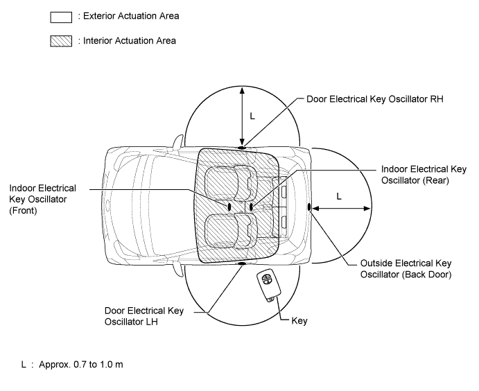
The special functions of the entry and start system only work when the key is in the actuation area formed by the 5 oscillators.
-
The indoor electrical key oscillator (front) and indoor electrical key oscillator (rear) form the interior actuation area.
-
The door electrical key oscillator LH, door electrical key oscillator RH and outside electrical key oscillator form the exterior actuation area.
-
Actuation Area
-
Actuation Area Details Interior The interior actuation area of the indoor electrical key oscillators (front, rear) is formed when the driver door is opened or closed, when the engine switch is pressed, when a warning is activated, or when the lock sensor is on, when the brake pedal (CVT) is press or when the clutch pedal (M/T) is pressed. Exterior The exterior actuation area formed by the door electrical key oscillators (LH, RH) and outside electrical key oscillator (back door) is approximately 0.7 to 1.0 m (2.3 to 3.3 ft.) from the outside handle of the front doors, or the center of the rear bumper. Front Door Around The exterior actuation area of the door electrical key oscillators (LH, RH) is formed by transmitting a request signal every 0.25 seconds while the engine switch is OFF and each door is locked. In this way it detects the proximity of a key. When locking the door using the lock switch on the outer door handle, the actuation area is formed when the lock switch is pressed. Back Door Around
-
The exterior actuation area of the outside electrical key oscillator (back door) is formed when the back door opener switch is on.
-
The exterior actuation area of the outside electrical key oscillator (back door) is formed when the back door lock switch is on.
-
-
SYSTEM CONTROL
-
Start Function
-
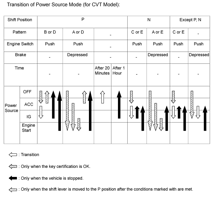
The start function has different power source patterns to suit the brake pedal state and shift lever position (for CVT models).
Pattern Brake Pedal Shift Lever Power Source Pattern A Depressed P or N Position
-
When the engine switch is pushed once.
-
OFF → IG-ON (after the engine is started)
B Not Depressed P Position
-
Each time the engine switch is pushed.
-
OFF → ACC → IG-ON → OFF
C Except P Position
-
Each time the engine switch is pushed.
-
OFF → ACC → IG-ON → ACC
D - P Position
-
When the engine switch is pushed in the IG-ON condition.
-
IG-ON (engine is started or not started) → OFF
E - Except P Position
-
When the engine switch is pushed in the IG-ON condition.
-
IG-ON (engine is started or not started) → ACC
Note
-
Normally, the operation of the engine switch is disabled while the vehicle is being driven. However, in an emergency, by pushing the engine switch for approximately 2 seconds or more or pushing the engine switch 3 times or more in a row, the driver can stop the engine while the vehicle is in motion.
-
If no signals are transmitted to the power management control ECU due to malfunctions in the stop light switch or park/neutral position switch assembly, the engine may not start when the engine switch is pressed with the brake pedal depressed. In such cases, performing the following procedure may enable the engine to start: 1) press the engine switch to turn the power source from OFF to ACC, and 2) press the engine switch again and hold it for 15 seconds or more.
-
The above 2 operations must be applied only in emergency situations. Under normal conditions, the engine must not be stopped by pressing the engine switch during while or started without depressing the brake pedal when the shift lever is in any position other than P or N.
-
-
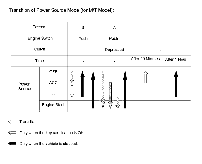
The start function has different power source patterns to suit the clutch pedal (for M/T models).
Pattern Clutch Pedal Power Source Pattern A Depressed
-
When the engine switch is pushed once.
-
OFF → IG-ON (after the engine is started)
B Not Depressed
-
Each time the engine switch is pushed.
-
OFF → ACC → IG-ON → OFF
Note
-
Normally, the operation of the engine switch is disabled while the vehicle is being driven. However, in an emergency, by pushing the engine switch for approximately 2 seconds or more or pushing the engine switch 3 times or more in a row, the driver can stop the engine while the vehicle is in motion.
-
If no signals are transmitted to the power management control ECU due to malfunctions in the clutch switch, the engine may not start when the engine switch is pressed with the clutch pedal depressed. In such cases, performing the following procedure may enable the engine to start: 1) press the engine switch to turn the power source from OFF to ACC, and 2) press the engine switch again and hold it for 15 seconds or more.
-
The above 2 operations must be applied only in emergency situations. Under normal conditions, the engine must not be stopped by pressing the engine switch while driving or started without depressing the clutch pedal.
-
-
Transition of the power source when the key does not operate properly due to a flat battery or radio jamming.
-
Unlock the door with the built-in mechanical key and get in the vehicle with the key carried by the user.
-
Bring the key ornament face into contact with the front face of the engine switch with the brake pedal depressed (M/T: Clutch Pedal).
-
Release the brake pedal within approximately 10 seconds after the buzzer in the combination meter sounds, and press the engine switch.
-
Each time the engine switch is pressed, the power source is turned from OFF to ACC, ACC to IG ON, and then IG ON to OFF.
-
-
Engine start-up when the key does not operate properly due to a flat battery or radio jamming.
-
Unlock the door with the built-in mechanical key and get in the vehicle with the key carried by the user.
-
Bring the key ornament face into contact with the front face of the engine switch with the brake pedal depressed (M/T: Clutch Pedal) when the shift lever is in P* or N*.
-
Press the engine switch with the brake pedal (M/T: Clutch Pedal) depressed within approximately 10 seconds after the buzzer in the combination meter sounds and the engine switch indicator light turns green.
-
The engine starts when the engine switch is pressed.
*: Models with CVT
-
-
-
Entry Unlock
-
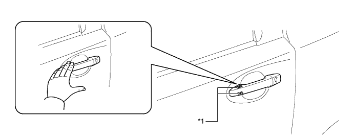
While the user carries the key in the exterior actuation area, and the driver door outside handle is held (the back side of the handle is touched), the door unlock sensor built into the handle detects it and the doors are unlocked.
-
When the doors are unlocked, the hazard warning lights flash twice as an answer back.
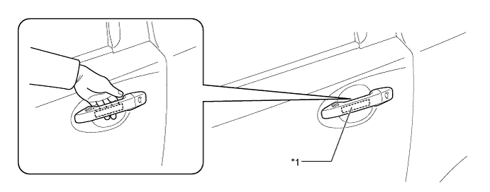
Text in Illustration *1 Unlock Sensor - -
-
-
Entry Lock
-
When the user gets out of the vehicle while carrying the key and touches the lock sensor*1 of the door outside handle within the exterior actuation area with all the doors closed, the doors are locked.
-
When the user gets out of the vehicle while carrying the key and presses the back door lock switch*2 on the back door side handle within the back door exterior actuation area with all the doors closed, the doors are locked.
-
When the doors are locked, the hazard warning lights flash once as an answer back.
Tech Tips
*1: For vehicles equipped with the double locking system, the double locking system can be activated by touching the door lock sensor again within 5 seconds of the sensor being touched first time.
*2: For vehicles equipped with the double locking system, press the back door lock switch again within 5 seconds of the switch being pressed the first time.
Text in Illustration (Front Door Outside Handle:) *1 Lock Sensor - - 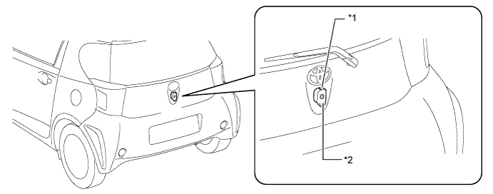
Text in Illustration (Back Door Outside Handle:) *1 Back Door Lock Switch *2 Back Door Outside Handle
-
-
Back Door Open
-
The back door is opened when the back door opener switch is pressed within the back door exterior detection area while the user is carrying the key.
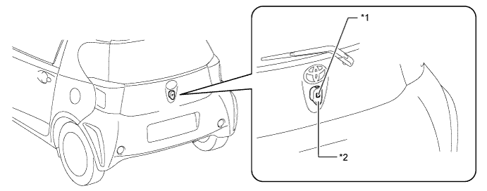
Text in Illustration *1 Back Door Opener Switch *2 Back Door Outside Handle
-
-
Warning
-
When any of the situations below occur, the entry and start system causes the smart key ECU assembly to sound a buzzer in the combination meter assembly and the wireless door lock buzzer and illuminate the engine switch illumination and smart warning light in order to alert the driver.
Situation Condition A The engine is left running and the shift lever is in a position other than P when the driver gets out of the vehicle (only for CVT models). B The driver door is opened while the steering is unlocked. C The engine is left running and the shift lever is in the P position when the driver gets out of the vehicle (only for CVT models). D A door is ajar and lock sensor is touched. E The engine is left running when a passenger gets out of the vehicle holding the key. F The key is not within the actuation areas. G The key is left in the vehicle interior and the lock sensor is touched. H The key battery is weak. I Steering lock does not release. J A malfunction of the steering lock ECU is detected. K The power management control ECU is malfunctioning. L An engine start method is displayed. M The vehicle is running with the key not in the vehicle interior. N The clutch start switch is malfunctioning (only for M/T models). -
There are 2 patterns for situation A.
-
Pattern 1: When the engine is left running and the shift lever is in a position other than P, the driver opens the door and attempts to get out of the vehicle. In this situation, the following control is performed:
Possible Effects without Warning Sudden vehicle start, Vehicle theft, Vehicle roll-away Warning Active Condition
-
The warning is activated when all of the following conditions are met:
-
Power source is in a mode other than OFF.
-
Shift lever is in any position except "P".
-
Vehicle speed is 0.
-
Driver door is opened.
Warning Method Combination Meter Assembly Buzzer Continuous sounds Smart Warning Light - Wireless Door Lock Buzzer - Engine Switch Illumination - Warning Stop Condition
-
The warning is stopped when one of the following conditions is met:
-
Power source is OFF.
-
Shift lever is "P".
-
Vehicle speed is above 0.
-
Driver door is closed.
-
-
Pattern 2: Under the conditions of pattern 1, the driver closes the door and attempts to leave the vehicle holding the key. In this situation, the following control is performed:
Possible Effects without Warning Sudden vehicle start, Vehicle theft, Vehicle roll-away Warning Active Condition
-
The warning is activated when all of the following conditions are met:
-
Power source is in a mode other than OFF.
-
Shift lever is in any position except "P".
-
Vehicle speed is 0.
-
Driver door is opened → closed.
-
Key is not in the vehicle interior.
Warning Method Combination Meter Assembly Buzzer Continuous sounds Smart Warning Light Flashes Wireless Door Lock Buzzer Continuous sound Engine Switch Illumination - Warning Stop Condition
-
The warning is stopped when one of the following conditions is met:
-
Power source is OFF.
-
Vehicle speed is above 0. (Only the combination meter assembly buzzer and the wireless door lock buzzer stop sounding)
-
Shift lever is in "P". (Only the combination meter assembly buzzer and the wireless door lock buzzer stop sounding)
-
Key is in the vehicle interior.
-
-
In the situation B (The driver door is opened while the steering is unlocked) the following control is performed.
Possible Effects without Warning Vehicle theft Warning Active Condition
-
The warning is activated when one of the following conditions is met:
-
Power source is ACC and the driver door is opened.
-
Power source is OFF, the steering is unlocked and the driver door is opened.
Warning Method Combination Meter Assembly Buzzer Continuous sounds at short and even intervals Smart Warning Light - Wireless Door Lock Buzzer - Engine Switch Illumination - Warning Stop Condition
-
The warning is stopped when one of the following conditions is met:
-
Power source is IG-ON or driver door is closed.
-
Power source is OFF and steering is locked.
-
-
There are 2 patterns for situation C.
-
Pattern 1: When the engine is left running and the shift lever is in the P position, the driver closes the driver's door and attempts to leave the vehicle while holding the key. In this situation, the following control is performed:
Possible Effects without Warning Vehicle theft, Engine cannot be restarted, Discharged battery Warning Active Condition
-
The warning is activated when all of the following conditions are met:
-
Power source is in a mode other than OFF
-
Shift lever is in "P".
-
Key is not in the vehicle interior.
-
Driver door is opened R closed.
Warning Method Combination Meter Assembly Buzzer Sounds once Smart Warning Light Flashes Wireless Door Lock Buzzer Sounds 3 times Engine Switch Illumination - Warning Stop Condition
-
The warning is stopped when one of the following conditions is met:
-
Power source is OFF.
-
Key is in the vehicle interior.
-
-
Pattern 2: Under the conditions of pattern 1, the driver touches the lock sensor. In this situation, the following control is performed:
Possible Effects without Warning Vehicle theft, Discharged battery Warning Active Condition
-
The warning is activated when all of the following conditions are met:
-
Power source is in a mode other than OFF.
-
Shift lever is in "P".
-
All doors are closed.
-
The key is not in the vehicle interior (within one of the actuation areas).
Warning Method Combination Meter Assembly Buzzer Sounds once Smart Warning Light Flashes for 60 seconds Wireless Door Lock Buzzer Sounds for 10 seconds Engine Switch Illumination - Warning Stop Condition
-
The warning is stopped when one of the following conditions is met:
-
Power source is OFF and the key is not within the actuation areas.
-
Key is in the vehicle interior.
-
Shift lever is in any position except "P".
-
Any door is open.
-
-
In the situation D (A door is ajar and lock sensor is touched) the following control is performed.
Possible Effects without Warning Vehicle theft Warning Active Condition
-
The warning is activated when all of the following conditions are met:
-
Power source is OFF.
-
Any door is opened.
-
Lock sensor is on.
Warning Method Combination Meter Assembly Buzzer - Smart Warning Light - Wireless Door Lock Buzzer Sounds for 10 seconds Engine Switch Illumination - Warning Stop Condition
-
The warning is stopped when one of the following conditions is met:
-
Power source is in a mode other than OFF.
-
All doors are closed.
-
Wireless door lock function is unlocked.
-
Entry unlock is operated.
-
-
In the situation E (The engine is left running and when a passenger gets out of the vehicle holding the key) the following control is performed.
Possible Effects without Warning Engine cannot be restarted Warning Active Condition
-
The warning is activated when all of the following conditions are met:
-
Power source is in a mode other than ON.
-
Door except driver door is opened →closed.
-
Vehicle speed is 0.
-
Key is not in the vehicle interior.
Warning Method Combination Meter Assembly Buzzer Sounds once Smart Warning Light Flashes Wireless Door Lock Buzzer Sounds 3 times Engine Switch Illumination - Warning Stop Condition
-
The warning is stopped when one of the following conditions is met:
-
Power source is OFF.
-
Vehicle speed is above 0.
-
Key is in the vehicle interior.
-
-
In the situation F (The key is not within the actuation areas) the following control is performed.
Possible Effects without Warning Confuses the user Warning Active Condition
-
The warning is activated when all of the following conditions are met:
-
Key is not in the vehicle interior.
-
Engine switch is pushed.
Warning Method Combination Meter Assembly Buzzer Sounds once Smart Warning Light Flashes for 15 seconds Wireless Door Lock Buzzer - Engine Switch Illumination - Warning Stop Condition
-
The warning is stopped when one of the following conditions is met:
-
Key is in the vehicle interior.
-
Engine switch is pushed.
-
-
In the situation G (The key is left in the vehicle interior and the lock sensor is touched) the following control is performed.
Possible Effects without Warning Vehicle theft Warning Active Condition
-
The warning is activated when all of the following conditions are met:
-
Power source is OFF.
-
All doors are closed.
-
Key is left in the vehicle interior.
-
Lock sensor is on.
-
Any door is unlocked.
Warning Method Combination Meter Assembly Buzzer Sounds once Smart Warning Light - Wireless Door Lock Buzzer Sounds for 10 seconds Engine Switch Illumination - Warning Stop Condition
-
The warning is stopped when one of the following conditions is met:
-
Power source is ON.
-
Any door is open.
-
The key is in the exterior actuation area and the entry lock operation is performed.
-
-
In the situation H (The key battery is weak) the following control is performed.
Possible Effects without Warning Entry and start system does not function Warning Active Condition
-
The warning is activated when all of the following conditions are met:
-
Power source switches to OFF after being left in IG-ON for over 20 minutes.
-
Key battery voltage is low.
Warning Method Combination Meter Assembly Buzzer Sounds once Smart Warning Light - Wireless Door Lock Buzzer - Engine Switch Illumination - -
-
In the situation I (Steering lock does not release) the following control is performed.
Possible Effects without Warning Steering usability function Warning Active Condition The steering lock does not release, thus the engine is prevented from starting. Warning Method Combination Meter Assembly Buzzer Sounds once Smart Warning Light - Wireless Door Lock Buzzer - Engine Switch Illumination The green indicator blinks at 1-second intervals. (It goes off automatically after 30 seconds.) Warning Stop Condition The engine switch is pressed while the steering wheel is tuned left and right, and the steering lock successfully disengages. -
In the situation J (A malfunction of the steering lock ECU is detected) the following control is performed.
Possible Effects without Warning Malfunction detection Warning Active Condition A malfunction of the steering lock ECU is detected. Warning Method Combination Meter Assembly Buzzer Sounds once Smart Warning Light - Wireless Door Lock Buzzer - Engine Switch Illumination The amber indicator blinks at 2-second intervals. (It goes off automatically after 15 seconds.) Warning Stop Condition The steering lock ECU returns normal. -
In the situation K (The power management control ECU is malfunctioning) the following control is performed.
Possible Effects without Warning Malfunction detection Warning Active Condition A malfunction of the power management control ECU is detected. Warning Method Combination Meter Assembly Buzzer - Smart Warning Light - Wireless Door Lock Buzzer - Engine Switch Illumination The amber indicator blinks at 2-second intervals. (It goes off automatically after 15 seconds.) Warning Stop Condition The power management control ECU returns normal. -
In the situation L (An engine start method is displayed) the following control is performed.
Possible Effects without Warning Usability function Warning Active Condition
-
The warning is activated when all of the following conditions are met:
-
Engine immobiliser is activated.
-
Key is not in the vehicle interior.
-
Key code verification error occurs twice when the engine switch is pushed or doors are unlocked using a mechanical key.
-
Engine switch is pushed.
Warning Method Combination Meter Assembly Buzzer Sounds once Smart Warning Light - Wireless Door Lock Buzzer - Engine Switch Illumination - -
-
In the situation M (The vehicle is running with the key not in the vehicle interior) the following control is performed.
Possible Effects without Warning Engine cannot be restarted. Warning Active Condition
-
The warning is activated when all of the following conditions are met:
-
Engine is running.
-
Key is not in the vehicle interior.
-
Vehicle speed is detected.
Warning Method Combination Meter Assembly Buzzer Sounds once Smart Warning Light Flashes Wireless Door Lock Buzzer - Engine Switch Illumination - Warning Stop Condition
-
The warning is stopped when one of the following conditions is met:
-
Power source is OFF.
-
Key is in the vehicle interior.
-
-
In the situation N (The clutch start switch is malfunctioning) the following control is performed.
Possible Effects without Warning Malfunction detection Warning Active Condition
-
The warning is activated when all of the following conditions are met:
-
Power source is OFF.
-
Clutch start switch remains ON for 5 minutes or more.
-
Driver door is closed → opened.
Warning Method Combination Meter Assembly Buzzer Sounds once Smart Warning Light - Wireless Door Lock Buzzer - Engine Switch Illumination The green indicator blinks. (It goes off automatically after 15 seconds.) Warning Stop Condition The clutch start switch returns normal. -
-
-
Battery Saving
Battery saving preserves the vehicle and key batteries. It is activated when the vehicle remains parked for a long time and when the key is left inside the exterior actuation area.
When the vehicle remains parked for a long time.
-
No response from key for more than 5 days
-
Door electrical key oscillator and outside electrical key oscillator stop emitting signals for creating the actuation area.
-
These controls are stopped when one of the following conditions is met:
-
The doors are locked or unlocked using wireless remote control.
-
The doors are locked or unlocked by touching the lock/unlock sensor on the driver door.
-
The doors are locked by pressing the back door lock switch.
-
The back door is opened by pressing the back door opener switch.
-
A door is locked or unlocked using the mechanical key.
-
Door is opened → closed.
-
No response from key for more than 14 days
-
Door electrical key oscillator and outside electrical key oscillator stop emitting signals for creating the actuation area.
-
Door lock sensor and unlock sensor are disabled.
When the key is left within the exterior detection area.
-
This state continues longer than 10 minutes
-
Electrical key oscillator that is detecting the key stops emitting signals for creating the actuation area.
-
The control is stopped when one of the following conditions is met:
-
The doors are locked or unlocked using wireless remote control.
-
The doors are locked or unlocked by touching the lock/unlock sensor on the front door.
-
The doors are locked by pressing the back door lock switch.
-
The back door is opened by pressing the back door opener switch.
-
A door is locked or unlocked using the mechanical key.
-
-
-
FUNCTION
-
Entry Function
-
The entry function consists of the following functions:
Function Outline Wireless Door Lock Control This function is a convenient system for locking and unlocking all the doors at a distance. The operation of this function is the same as that in the wireless door lock control system. Entry Illumination When a key enters the exterior actuation area of door electrical key oscillators (LH and RH) the personal light illuminate. Entry Unlock When a key is located in the exterior actuation area of any electrical key oscillator (driver, front passenger, or back door) and the engine switch is OFF, all doors can be unlocked by simply touching the unlock sensor. Entry Lock When a key is located in the exterior actuation area of any electrical key oscillator (driver, front passenger, or back door) and the engine switch is OFF, all doors can be locked by simply touched the lock sensor or pressing the back door lock switch. Back Door Open When a key is in an exterior actuation area of the outside electrical key oscillator (back door), the back door opens manually by simply pressing the back door opener switch. Prevention of Key Confinement The key confinement prevention function prevents the key from being locked inside the vehicle. This function operates in 2 different situations: keyless lock, lock sensor. Warning When any of the situations below occur, the entry and start system causes the smart key ECU assembly to sound the buzzer in the combination meter assembly and the wireless door lock buzzer in order to the alert the driver. Battery Saving If the key remains within the exterior actuation area of any electrical key oscillator (driver, front passenger, or back door), the system maintains periodic communication with key. Therefore, if the vehicle remains parked in that state for a long time, the key battery and the vehicle battery could be drained. Key Cancel
-
The following key functions can be cancelled by following certain procedures.
-
Entry Unlock/Lock
-
Back Door Open
-
Prevention of Key Confinement
-
Warning
Key Code Registration A total of 7 keys can be registered. Enables the registering (writing and storing) of transmitter recognition codes in the EEPROM that is contained in the smart key ECU assembly. -
-
-
Wireless Door Lock Control Function
The wireless door lock control function has the following functions and customizes:
Function Outline Customizable* All Doors Lock Pressing the LOCK button to lock all doors. Default setting is on All Doors Unlock Pressing the UNLOCK button to unlock all doors. Default setting is on Answer Back When the doors are being locked or unlocked through the operation of the key, the hazard lights blinks once during locking and twice during unlocking. Also, the answer back function operates when the doors are locked by the auto relock function. Default setting is on Automatic Relock If none of the doors are opened within 30 seconds after they are unlocked using the wireless door lock remote control, all the doors will be locked again automatically. Default setting is described to the left. Security Sends a door lock/unlock operation request signal as a rolling code. Not Customizable Door Ajar Warning If any door is open or ajar, pressing the LOCK button of the key will cause the wireless door lock buzzer to sound for about 10 seconds as a warning. Not Customizable Tech Tips
*: The customize setting can be turned ON/OFF using the customized body electronics system. For details, refer to Repair Manual.
-
Key Cancel
-
It is possible to deactivate the following entry and start system functions.
-
Entry Lock
-
Entry Unlock
-
Back Door Open
-
Prevention of Key Confinement
-
Warning
-
-
Key cancel is operated when certain operations are performed with the vehicle in the following condition:
-
Power source is OFF.
-
Driver door is closed.
-
Driver door is unlocked.
-
-
The operation procedure is as follows:
-
Unlock once with the UNLOCK button of the key.
-
Open the driver door within 5 seconds.
-
Unlock twice with the UNLOCK button of the key within 5 seconds.
-
Repeat open → close twice for the driver door within 30 seconds, and open again (Driver Door: Open → Close → Open → Close → Open).
-
Unlock twice with the UNLOCK button of the key within 30 seconds.
-
Repeat open → close once for the driver door within 30 seconds, and open again (Driver Door: Open → Close → Open).
-
Close the driver door within 5 seconds.
When key cancel is activated, the wireless door lock buzzer sounds once. To return to the original condition, perform the procedures again. When key cancel is returned, the wireless door lock buzzer sounds twice.
-
-
-
Key Code Registration Function
The table below shows the three special coded ID registration function modes through which up to seven different codes can be registered. The codes are electronically registered (written to and stored) in the EEPROM. For details of the recognition code registration procedure, refer to the Repair Manual.
Mode Function Rewrite Erases all previously registered codes and registers only the newly received codes. This mode is used whenever a transmitter or the integration relay is replaced. Add Adds a newly received code while preserving previously registered codes. This mode is used when adding a new transmitter. Confirm Confirms how many codes are currently registered. When adding a new code, this mode is used to check how many codes already exist.
-
-
CONSTRUCTION
-
Key
-
The key consists of a mechanical key, transmitter for the wireless door lock control, transceiver for the entry function and transponder chip for the engine immobiliser function.
-
This mechanical key operates the driver door lock cylinder, but cannot be used to start the engine. When the mechanical key is used, the cap of the driver door lock cylinder must be removed.
-
The transmitter for the wireless door lock control has a LOCK button and UNLOCK button.
-
The transceiver of the key receives the signals from the oscillators and returns the ID code to the door control receiver.
-
The transponder chip for the engine immobiliser function returns a signal to the engine switch as a response to the radio wave it received from the engine switch.
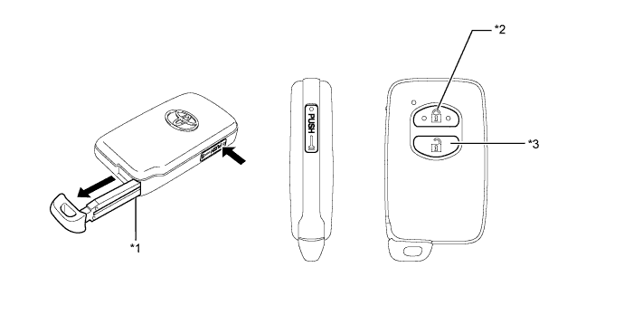
Text in Illustration *1 Mechanical Key *2 LOCK Button *3 UNLOCK Button - -
-
-
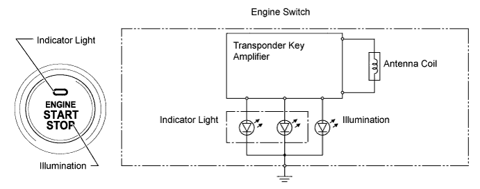
Engine Switch
-
The engine switch consists of a momentary type switch, indicator light (amber and green color LEDs), illumination, antenna coil and transponder key amplifier.
-
The driver can determine the present power source and check whether the engine can start or not in accordance with the illumination state of the indicator light.
-
When the power management control ECU detects an abnormality with the entry and start system, it makes the amber indicator light flash. If the engine is stopped in this state, it might not be possible to restart it.
Power Source Condition Indicator Light Condition Brake pedal not depressed (for CVT model) Clutch pedal not depressed (for M/T model) OFF OFF ACC, IG-ON ON (Amber) Engine Running OFF Steering lock not unlocked Flashes (Green) for 15 seconds Entry and Start System Malfunction Flashes (Green) for 15 seconds Clutch Start Switch Signal Malfunction - Flashes (Green) for 15 seconds Power Source Condition Indicator Light Condition Brake pedal depressed with shift lever in "P" or "N" (for CVT model) Clutch pedal depressed (for M/T model) OFF ON (Green) ACC, IG-ON ON (Green) Engine Running OFF Steering lock not unlocked Flashes (Green) for 15 seconds Entry and Start System Malfunction Flashes (Amber) for 15 seconds Clutch Start Switch Signal Malfunction - Flashes (Green) for 15 seconds
-
-
-
DIAGNOSIS
-
Start Function
-
The power management control ECU and smart key ECU assembly can detect malfunction in the entry and start system when the power source is in the IG-ON mode.
-
When the ECUs detect a malfunction, the amber indicator light of the engine switch flashes to warn the driver. At the same time, the ECUs store 5-digit Diagnostic Trouble Code (DTC) in their memories.
-
The indicator light warning continues for 15 seconds even after the engine switch is switched to OFF.
-
The 5-digit DTCs can be read after connecting an intelligent tester II to DLC3.
-
The entry and start system may not operate successfully if a malfunction occurs.
-
-