AIR CONDITIONING SYSTEM DETAILS
-
SYSTEM CONTROL
-
Control List
-
The air conditioning system uses the following types of control.
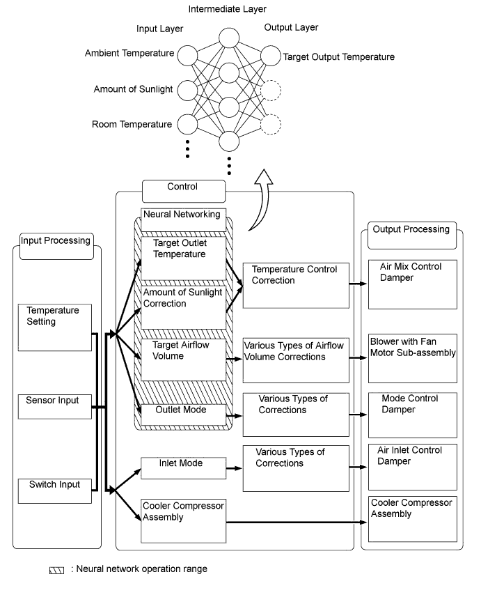
Control Outline Air Conditioning with without Automatic Manual Neural Network Control This control is capable of effecting complex control by artificially simulating the information processing method of the nervous system of living organisms in order to establish a complex input or output relationship that is similar to a human brain. ○ - - Outlet Air Temperature Control In compliance with the temperature set at the temperature control switch, the neural network control calculates the outlet temperature based on the input signals from various sensors. In addition, corrections in accordance with the signals from the evaporative temperature sensor and water temperature sensor are added to control the outlet air temperature. ○ - - Blower Control Controls the blower motor in accordance with the airflow volume that has been calculated by the neural network control based on the input signals from various sensors. ○ - - Air Outlet Control Automatically switches the outlets in accordance with the outlet mode ratio that has been calculated by the neural network control based on the input signals from various sensors. ○ - - Air Inlet Control Automatically controls the air inlet control damper in accordance with the airflow volume that has been calculated by the neural network control. ○ - - Variable Capacity Compressor Control Through the calculation of the target evaporator temperature based on various sensor signals, the air conditioning amplifier assembly optimally controls the discharge capacity by regulating the opening extent of the cooler compressor solenoid control valve. ○ - - PTC Heater Control* When the ignition switch is turned ON, and the blower motor is turned on, the air conditioning amplifier assembly turns on the PTC heater assembly if the conditions listed below are met.
-
Engine coolant temperature is below specified temperature.
-
Ambient temperature is below specified temperature.
-
Tentative air mix damper opening angle is above the specified value (MAX. HOT).
○ ○ ○ Rear Window Defogger & Mirror Heater Control When the ignition switch is turned ON, and the rear defogger switch is pushed, this system is activated to keep the defogger heater on for approximately 15 minutes. However, the operating time of the rear defogger may be extended up to approximately 45 minutes when the following requirements are met.
-
Ambient Temperature: -3°C or less
-
Vehicle Speed: 45 km/h (28 mph) or more
○ - - ○ : Equipped - : Not equipped
-
*: for Models with PTC heater
-
-
-
Neural Network Control
-
Previously, in automatic air conditioning systems without neural network control, the air conditioning amplifier determined the required outlet air temperature and blower air volume in accordance with the calculation formula that has been obtained based on information received from the sensors. However, because the senses of a person are rather complex, a given temperature is sensed differently, depending on the environment in which the person is situated. For example, a given amount of solar radiation can feel comfortably warm in a cold climate, or extremely uncomfortable in a hot climate. Therefore, as a technique for effecting a higher level of control, a neural network has been adopted in the automatic air conditioning system. With this technique, the data that has been collected under varying environmental conditions is stored in the air conditioning amplifier. The air conditioning amplifier can then effect control to provide enhanced air conditioning comfort.
-
The neural network control consists of neurons in the input layer, intermediate layer and output layer. The input layer neurons process the input data of the ambient temperature, the amount of sunlight, and the room temperature based on the outputs of the switches and sensors, and output them to the intermediate layer neurons. Based on this data, the intermediate layer neurons adjust the strength of the links among the neurons. The sum of these is then calculated by the output layer neurons in the form of the required outlet temperature, solar correction, target airflow volume and outlet mode control volume. accordingly, the air conditioning amplifier controls the servo motors and blower motor in accordance with the control volumes that have been calculated by the neural network control.
-
-
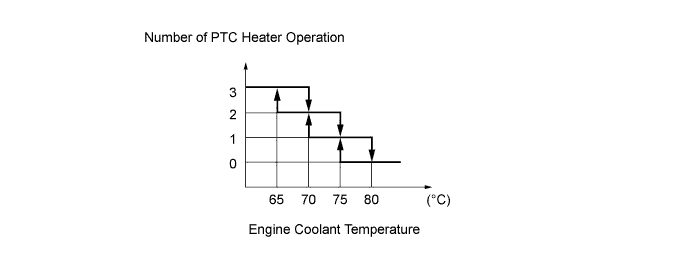
PTC Heater Control
-
The PTC heater is controlled by the air conditioning amplifier in accordance with the engine coolant temperature, engine speed, air mix setting, ambient temperature and electrical load (generator power ratio). For example, the number of the operating PTC heaters varies with engine coolant temperature as in the graph below.
-
-
-
CONSTRUCTION
-
Heater Control Panel (for Manual Control Type)
-
The rotary switch type heater control panel is used.
-
The new models use two cables on pulleys to operate the heater control panel and damper.
-
Five air outlet modes are provided on the control panel on the models with air conditioning. To realize finer mode settings, a positive feel is provided between the positions of these modes, thus realizing the high comfort level.
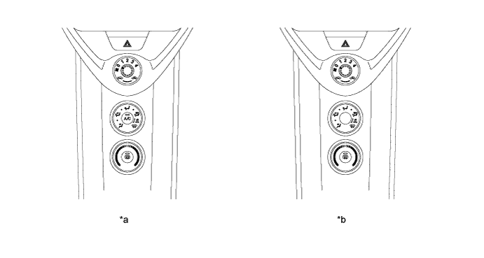
Text in Illustration *a Manual Air Conditioning Model *b Without Air Conditioning Model -
This cable is circular, and is placed around the cable pulleys that are provided at the heater control panel and the damper.
-
The operation of the heater control panel is transmitted to the damper via the control cable, which always moves in the pulling direction. Due to the consistent action point of the pulleys, the fluctuation of the operating effort has been minimized through the use of the pulleys. These measures have improved the ease of use and reduced the operating effort.
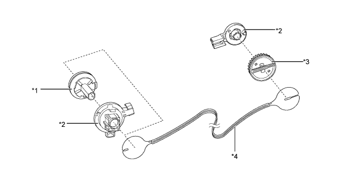
Text in Illustration *1 Pulley (Heater Control Panel Side) *2 Base of Pulley *3 Pulley (Damper Side) *4 Control Cable
-
-
Heater Control Panel (for Automatic Control Type)
-
The rotary switch and push switch type heater control panel is used.
-
This heater control panel use an LCD (Liquid Crystal Display) to display the set temperature, air outlet mode and blower speed to ensure excellent visibility.
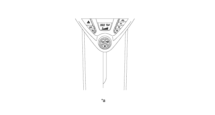
Text in Illustration *a Automatic Air Conditioning Model - -
-
-
Air Conditioning Unit Assembly
-
The center location air conditioning unit assembly, in which the No. 1 cooler evaporator sub-assembly and heater radiator unit sub-assembly are arranged longitudinally, is used.
-
The air conditioning unit assembly has been made more compact by incorporating the conventional blower fan unit into the center unit. The air conditioning unit assembly is located in the center area of the instrument panel. This provides sufficient foot space for the front passenger.
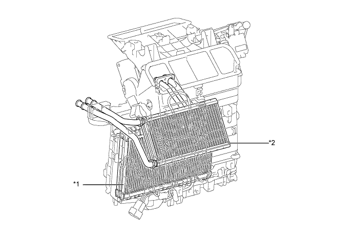
Text in Illustration *1 No. 1 Cooler Evaporator Sub-assembly *2 Heater Radiator Unit Sub-assembly
-
-
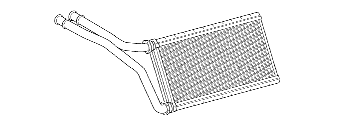
No. 1 Cooler Evaporator Sub-assembly
-
The RS (Revolutionary super-slim Structure) type No. 1 cooler evaporator sub-assembly is used.
-
By placing the tanks at the top and the bottom of the evaporator unit and adopting a micropore tube construction, the following effects have been realized:
-
The heat exchanging efficiency has been improved.
-
The temperature distribution has been made more uniform.
-
The evaporator has been made thinner.
-
-
The evaporator body has been coated with a type of resin is capable of preventing the growth of various bacteria which can produce a bad odor which can stick to the evaporator surfaces.
-
The substrate for this coating material includes a chromate-free layer for environmental protection.
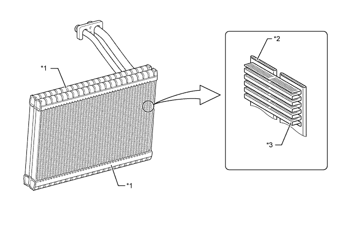
Text in Illustration *1 Tank *2 Micropore Tube *3 Cooling Fin - -
-
-
Evaporator Temperature Sensor
-
The evaporator temperature sensor detects the temperature of the cool air immediately past the No. 1 cooler evaporator sub-assembly in the form of resistance changes, and outputs it to the air conditioning amplifier.
-
-
Heater Radiator Unit Sub-assembly
-
A compact, lightweight and highly efficient SFA (Straight Flow Aluminum)-II type heater radiator unit sub-assembly is used.
-
-
Blower with Fan Motor Sub-assembly
-
The blower with fan motor sub-assembly has a built-in blower controller, and is controlled using duty control performed by the air conditioning amplifier.
-
Compact and lightweight fan blades are used for the blower with fan motor sub-assembly. Smooth airflow around the fan has further improved and the power consumption and noise generation have been reduced by rotating the motor at high speed.
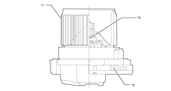
Text in Illustration *1 Fan Blade *2 Blower Controller (for Models with automatic air conditioning) *3 Blower Motor - -
-
-
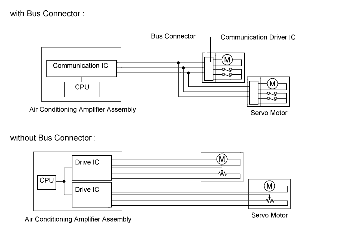
Bus Connector (Models with Automatic Air Conditioning)
-
The BUS connector is used in the wire harness connection that connects the servo motor from the air conditioning amplifier assembly.
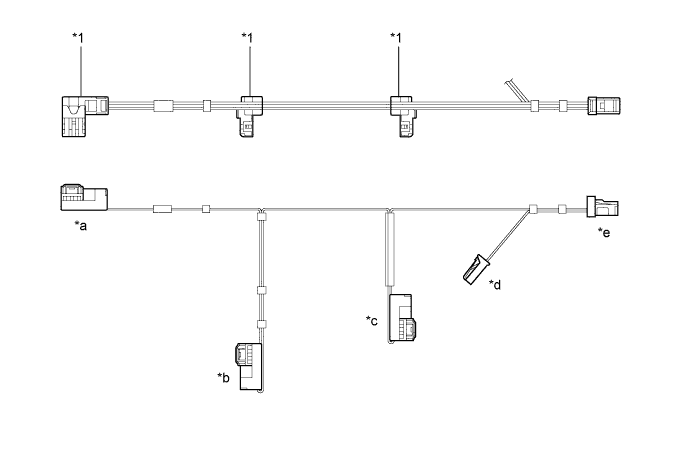
Text in Illustration *1 Bus Connector - - *a To Mode Control Servo Motor *b To Air Inlet Control Servo Motor *c To Air Mix Control Servo Motor *d To Evaporator Temp. Sensor *e To Air Conditioning Amplifier Assembly - - -
The BUS connector has a built-in driver IC which communicates with each servo motor connector, actuates the servo motor, and has a position detection function. This enables bus communication for the servo motor wire harness, for a more lightweight construction and a reduced number of wires.
-
-
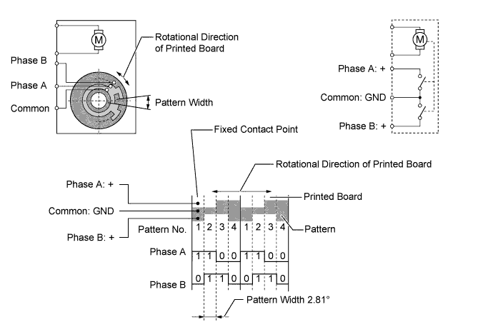
Servo Motor (Models with Automatic Air Conditioning)
-
In contrast to the previous type that detects the position by way of a potentiometer voltage, the pulse pattern type servomotor detects the relative position by way of the 2-bit on/off signals.
-
The forward and reverse revolutions of this motor are detected by way of two phases, A and B, which output four types of patterns. The air conditioning amplifier assembly counts the number of pulse patterns in order to determine the stopped position.
-
-
PTC Heater
-
The PTC (Positive Temperature Coefficient) heater is located above the heater radiator unit sub-assembly in the air conditioning unit assembly.
-
The PTC heater consists of a PTC element, aluminum fin and brass plate. When current is applied to the PTC element, it generates heat to warm the air that passes through the unit.
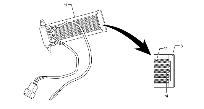
Text in Illustration *1 PTC Heater *2 Aluminum Fin *3 Brass Plate *4 PTC Element
-
-
Clean Air Filter
-
A pollen removal type clean air filter is used to remove dust, pollen and other micron particles from air entering from outside the vehicle to provide a comfortable cabin of clean air.
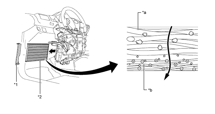
Text in Illustration *1 Air Filter Case *2 Clean Air Filter *a Large Foreign Object Layer *b Electret Layer Tech Tips
The filter should be changed at 30000 km (18000 miles) under normal conditions [cleaning interval: 15000 km (9000 miles)]. Under dusty conditions, the filter should be changed at 15000km (9000 miles) [cleaning interval: 7500 km (4500 miles)]. However, observation of these guidelines should depend on the usage conditions (or environment).
-
-
Cooler Condenser Assembly
-
A MF (Multi-Flow) type cooler condenser assembly is used. The cooler condenser assembly consists of two cooling portions: a condensing portion and a super-cooling portion, and gas-liquid separator (modulator) are integrated together. This cooler condenser assembly uses a sub-cool cycle that offers excellent heat-exchange performance.
-
In the sub-cool cycle, after the refrigerant passes through the condensing portion of the cooler condenser assembly, both the liquid refrigerant and the gaseous refrigerant that could not be liquefied are cooled again in the super-cooling portion. Thus, the refrigerant is sent to the No. 1 cooler evaporator sub-assembly in an almost completely liquefied state.
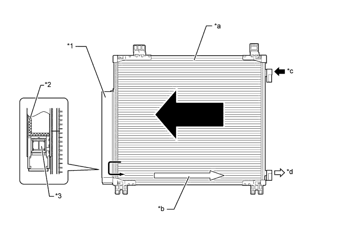
Text in Illustration *1 Modulator *2 Desiccant *3 Filter - - *s Condensing Portion *b Super-cooling Portion *c Gaseous Refrigerant *d Liquid Refrigerant Tech Tips
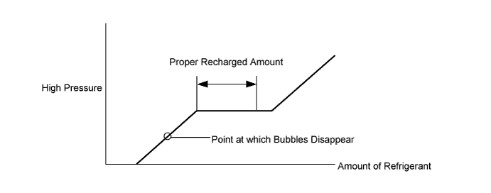
The point at which the air bubbles disappear in the refrigerant of the sub-cool cycle is lower than the proper amount of refrigerant with which the system must be filled. Therefore, if the system is recharged with refrigerant based on the point at which the air bubbles disappear, the amount of refrigerant would be insufficient. As a result, the cooling performance of the system would be affected. If the system is overcharged with refrigerant, this will also lead to reduced performance. For the proper method of verifying the amount of the refrigerant and for instructions on how to recharge the system with refrigerant, see the Repair Manual.
-
-
Cooler Compressor Assembly
-
Cooler Compressor Assembly
-
The cooler compressor assembly is continuously variable capacity type in which its capacity can be varied in accordance with the cooling load of the air conditioning.
-
The cooler compressor assembly consists of the A/C pulley with magnet clutch, shaft, lug plate, swash plate, piston, shoe, crank chamber, cylinder and solenoid control valve.
-
A solenoid control valve that adjusts the suction pressure so that the compressor capacity can be controlled as desired is provided.
-
The cooler compressor assembly has a flow volume sensing mechanism which uses a refrigerant flow volume sensor, oil separator mechanism, variable suction side throttle and solenoid control valve with CS valve. As a result, the cooling efficiency has been improved while simultaneously increasing the power saving ability.
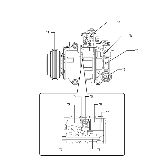
Text in Illustration *1 A/C Pulley with Magnet Clutch *2 Solenoid Control Valve *3 Crank Chamber *4 Shoe *5 Swash Plate *6 Piston *7 Cylinder *8 Lug Plate *9 Shaft - - *a Flow Volume Sensing Mechanism *b Oil Separator Mechanism *c Variable Suction Side Throttle - - -
-
Solenoid control valve with CS valve
-
If the vehicle has been left for a long time, the temperature of the cooler compressor assembly, which has the largest heat capacity among the air conditioning system devices (such as the cooler condenser assembly and No. 1 cooler evaporator sub-assembly), will decrease due to the differences of the heat capacities. At this time, refrigerant may accumulate inside the cooler compressor assembly. If this occurs, the cooler compressor assembly cannot increase its capacity until the liquid refrigerant is fully discharged. Since a conventional cooler compressor assembly has a single passage for discharging refrigerant, it takes several tens of seconds until the capacity is increased. In addition to the conventional discharge passage, the cooler compressor assembly used on iQ has another discharge passage that will open only when refrigerant accumulates inside the solenoid control valve. As a result, the time required for discharging the refrigerant has been significantly shortened and the immediate cooling effect has been further improved.
-
The CS valve is built into the shaft inside the solenoid control valve instead of being placed outside the solenoid control valve. This allows the refrigerant to discharge more easily and minimizes the size increase of the cooler compressor assembly.
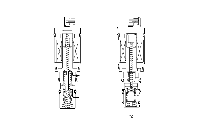
Text in Illustration *1 Solenoid Control Valve with CS Valve *2 Conventional Solenoid Control Valve 
Continuous Hole - - -
-
Flow volume sensing mechanism
-
Conventionally, the workload (compressor torque) of the cooler compressor assembly was estimated based on the current and high pressure of the solenoid control valve. The flow volume sensing mechanism used on the new iQ can estimate the compressor torque more accurately using a refrigerant flow volume sensor. Thus, load condition data of the cooler compressor assembly is used for engine controls as feedback with high accuracy, and the compressor is controlled efficiently, saving power while operating the air conditioning system.
-
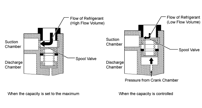
The cooler compressor assembly uses the refrigerant flow volume sensor, which detects the flow volume of discharged refrigerant based on the changes in the magnetic flux of a spool. The refrigerant passage becomes narrower at one point so that the differential pressure before and after that point changes depending on the flow volume of the refrigerant. The differential pressure is then introduced into the upper and lower sides of the spool to change the spool position. The magnetic sensor portion detects the position of the magnet built into the spool and converts it into the flow volume of the refrigerant. Then the compressor torque is calculated based on the flow volume of the refrigerant.
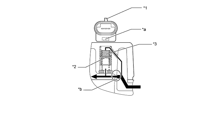
Text in Illustration *1 Refrigerant Flow Volume Sensor *2 Spool *3 Magnet - - *a Magnetic Sensor Portion *b Narrow Refrigerant Passage Flow of Refrigerant - - -
-
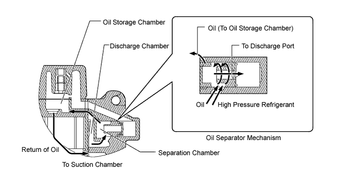
Oil separator mechanism
-
Conventionally, the cooler compressor assembly mixes oil into the refrigerant that is sucked into the compressor to ensure smooth sliding of each portion. Since the refrigerant containing oil is discharged from the cooler compressor assembly, the oil that does not contribute to the refrigerant effect circulates in addition to the refrigerant itself in the air conditioning system operation cycle. As a result, the cooling efficiency was compromised. By providing an oil separator in the cooler compressor assembly, most of the oil can be stored inside the cooler compressor assembly and most of the refrigerant can be circulated in the air conditioning system operation cycle. As a result, the cooling efficiency has been significantly improved and the air conditioning system also consumes less power as a result.
-
The oil separator mechanism uses a centrifugation method that has a high separation efficiency and separates the oil from the refrigerant in the separation chamber. The oil circulates inside the cooler compressor assembly along a route in the order of the separation chamber, oil storage chamber, suction chamber, cylinder and discharge chamber, then returns to the separation chamber. As a result, the mechanism prevents the oil from being discharged from the cooler compressor assembly.
Tech Tips
Centrifugation is a method to separate liquids with specific gravity difference using a force applied to the axis of rotation in the vertical direction (centrifugal force) by rotating them at high speed.
-
-
Variable Suction Side Throttle
-
The cooler compressor assembly uses the variable suction side throttle, which adjusts the refrigerant suction passage according to heat load or vehicle running conditions. When the capacity of the cooler compressor assembly is controlled, the throttle is closed according to the flow volume of refrigerant to reduce pulsation. At the maximum capacity of the cooler compressor assembly, the throttle is fully opened to prevent an increase in suction resistance of the cooler compressor assembly due to the throttle being closed.
-
-
-
Cooler (Room Temp. Sensor) Thermistor
-
The cooler (room temp. sensor) thermistor detects the room temperature based on changes in the resistance of its built-in thermistor and sends a signal to the air conditioning amplifier assembly.
-
-
Cooler (Ambient Temp. Sensor) Thermistor
-
The cooler (ambient temp. sensor) thermistor detects the ambient temperature based on changes in the resistance of its built-in thermistor. This signal is transmitted from the combination meter assembly to the air conditioning amplifier assembly through CAN communication.
-
-
Automatic Light Control Sensor
-
The automatic light control sensor detects (in the form of changes in the current that flows through the built-in photo diode) the changes in the amount of sunlight and outputs these sunlight strength signals to the air conditioning amplifier assembly.
-
-
-
OPERATION
-
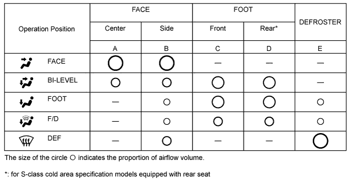
Mode Position and Door Operation
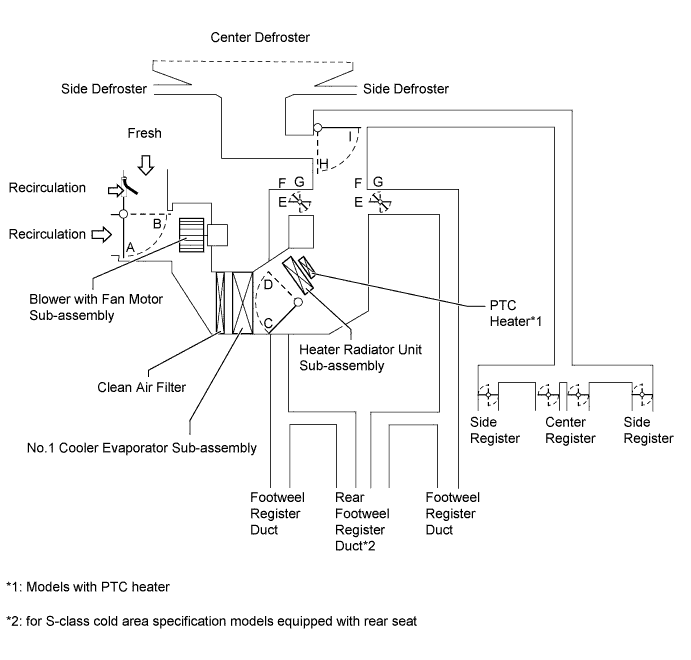
Control Damper Operation Position Damper Position Operation Air Inlet Control Damper FRESH A Brings in fresh air. RECIRC B Recirculates internal air. Air Mix Control Damper MAX COLD - MAX HOT C, D Varies the mixture ratio of the fresh air and the recirculation air in order to regulate the temperature continuously from HOT to COLD. Mode Control Damper 
DEF G, I Defrosts the windshield through the center defroster, side defroster and side register. 
FOOT/DEF F, I Defrosts the windshield through the front defroster, side defroster and side register, while air is also blown out from the footwell register duct and rear footwell register duct*. 
FOOT E, I Air blows out of the footwell register duct, rear footwell register duct* and side register. In addition, air blows out slightly from the front defroster and side defroster. 
BI-LEVEL F, H Air blows out of the center register, side register, footwell register and rear footwell register duct*. 
FACE G, H Air blows out of the center register and side register.
-
*: for S-class cold area specification models equipped with rear seat
-
-
Air Outlets and Airflow Volume
-
Compressor Operation (Variable Capacity Operation)
-
A solenoid control valve is connected to the suction passage, the discharge passage and the crank chamber passage.
-
The solenoid control valve operates under duty cycle control in accordance with the signals from air conditioning amplifier.
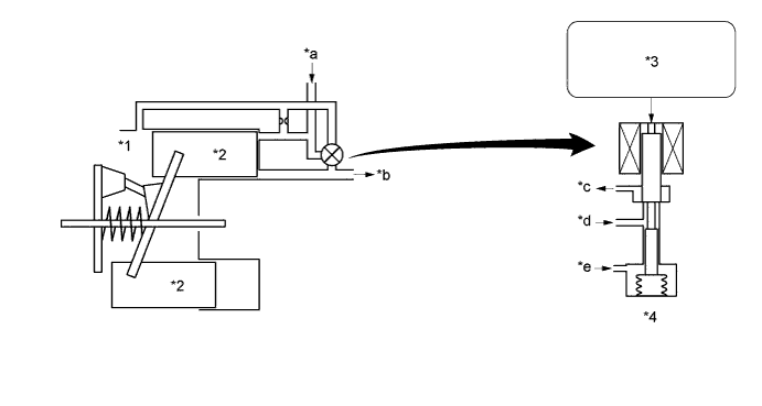
Text in Illustration *1 Crank Chamber *2 Piston *3 Air Conditioning Amplifier Assembly *4 Solenoid Control Valve *a Suction *b Discharge *c Crank Chamber Pressure *d Discharge Pressure *e Suction Pressure - - -
When the solenoid control valve closes (solenoid coil is energized), a difference in pressure is created and the pressure in the crank chamber decreases. Then, the pressure that is applied to the right side of the piston becomes greater than the pressure that is applied to the left side of the piston. This compresses the spring and tilts the swash plate. As a result, the piston stroke increases and the discharge capacity increases.
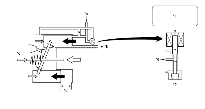
Text in Illustration *1 Air Conditioning Amplifier Assembly *2 Solenoid Control Valve *a Suction *b Discharge *c Crank Chamber Pressure + Spring Force *d Piston Stroke : Large *e Discharge Pressure - - -
When the solenoid control valve opens (solenoid coil is not energized), the difference in pressure disappears. Then, the pressure that is applied to the left side of the piston becomes the same as the pressure that is applied to the right side of the piston. Thus, the spring elongates and eliminates the tilt of the swash plate. As a result, there is no piston stroke and the discharge capacity is reduced.
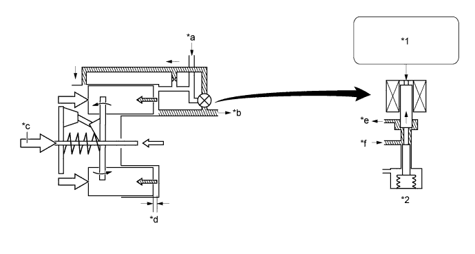
Text in Illustration *1 Air Conditioning Amplifier Assembly *2 Solenoid Control Valve *a Suction *b Discharge *c Crank Chamber Pressure + Spring Force *d Piston Stroke : Small *e Crank Chamber Pressure *f Discharge Pressure
-
-
-
DIAGNOSIS
-
The air conditioning amplifier assembly has a diagnosis function. It stores a record of any air conditioning system failures in memory in the form of DTCs.
-
There are 2 methods for reading DTCs. One is to use an intelligent tester II and the other is to read the DTCs using the heater control panel display (Only for models with automatic air conditioning). For details, refer to the Repair Manual.
-