AIR CONDITIONING SYSTEM PARTS LOCATION
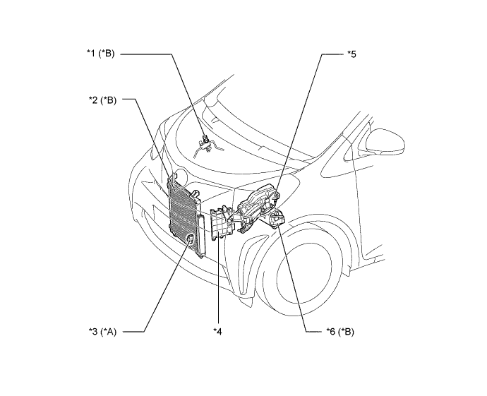
| *A | Models with Automatic Air Conditioning | *B | Models with Air Conditioning |
| *1 | A/C Pressure Sensor (Air Conditioning Tube Assembly) | *2 | Cooler Condenser Assembly |
| *3 | Cooler (Ambient Temp. Sensor) Thermistor | *4 | ECM |
| *5 |
|
*6 |
|
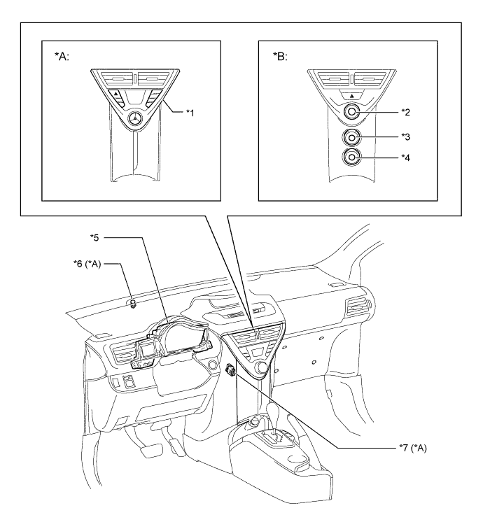
| *A | Models with Automatic Air Conditioning | *B | Models with Manual Air Conditioning and without Air Conditioning |
| *1 | Heater Control Panel (Instrument Cluster Finish Panel Assembly) | *2 | No. 2 Heater Control Sub-assembly |
| *3 |
|
*4 |
|
| *5 | Combination Meter Assembly | *6 | Automatic Light Control Sensor |
| *7 | Cooler (Room Temp. Sensor) Thermistor | - | - |
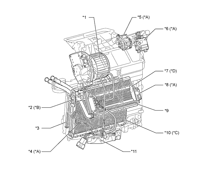
| *A | Models with Automatic Air Conditioning | *B | Except for Models with Automatic Air Conditioning |
| *C | Models with Air Conditioning | *D | Models with PTC Heater |
| *1 |
|
*2 | Blower Resister |
| *3 | Clean Air Filter | *4 | Evaporator Temperature Sensor (No. 1 Cooler Thermistor) |
| *5 | Airmix Damper Servo Sub-assembly | *6 | Damper Servo Sub-assembly |
| *7 | PTC Heater (Quick Heater) | *8 | Mode Damper Servo Sub-assembly |
| *9 | Heater Radiator Unit Sub-assembly | *10 | No. 1 Cooler Evaporator Sub-assembly |
| *11 | Air Conditioning Amplifier Assembly | - | - |