LIGHTING SYSTEM DETAILS
-
FUNCTION OF MAIN COMPONENTS
-
Daytime Running Light System
Component Function Main Body ECU (Instrument Panel Junction Block Assembly) The main body ECU (instrument panel junction block assembly) receives various signals and illuminates the daytime running light. Headlight Dimmer Switch Assembly Light Control Switch The light control switch outputs a light control signal and transmits it to the main body ECU (instrument panel junction block assembly). ECM The ECM outputs an engine speed signal and transmits it to the main body ECU. Electric Parking Brake ECU Transmits the parking brake operation signal to the main body ECU (instrument panel junction block assembly) -
Automatic Light Control System
Component Function Main Body ECU (Instrument Panel Junction Block Assembly) The main body ECU (instrument panel junction block assembly) receives various signals and illuminates the headlights, taillights, clearance lights, and license plate lights. Headlight Dimmer Switch Assembly Light Control Switch The light control switch transmits an AUTO position signal to the main body ECU (instrument panel junction block assembly). Rain Sensor The rain sensor detects the ambient light level. -
HID Headlight System
Component Function Main Body ECU (Instrument Panel Junction Block Assembly) The main body ECU (instrument panel junction block assembly) receives the HEAD position signal and transmits a signal to the light control ECU. Headlight Dimmer Switch Assembly Light Control Switch The light control switch transmits a HEAD position signal to the main body ECU. Headlight Unit Light Control ECU The light control ECU transforms battery voltage to a high voltage of up to 30000 V and applies it to the discharge bulbs in order to illuminate them. Discharge Bulb The discharge bulb light shines ahead over a broader area and further forward, increasing the area visible to the driver. -
Automatic Headlight Beam Level Control System
Component Function Headlight Swivel ECU Assembly The headlight swivel ECU assembly receives various signals, calculates the target lighting angle, and actuates the headlight leveling motor. Headlight Unit Headlight Leveling Motor -
Based on the signals received from the headlight swivel ECU assembly, the motors move the reflectors in the headlights.
-
Uses a step motor to precisely regulate the angle of the reflectors.
Rear Height Control Sensor Sub-assembly Detects the height of the vehicle. Skid Control ECU Transmits the speed sensor signal to the headlight swivel ECU assembly. ECM Transmits the engine running status signal to the headlight swivel ECU assembly. Main Body ECU (Instrument Panel Junction Block Assembly) Transmits the headlight status signal. Combination Meter Assembly AFS OFF Indicator Light If the system malfunctions, the meter ECU alerts the driver by blinking the AFS OFF indicator light in accordance with the signal from the headlight swivel ECU assembly. -
-
Intelligent AFS
Component Function Headlight Swivel ECU Assembly The headlight swivel ECU assembly receives various signals, calculates the target lighting angle, and actuates the headlight swivel motor. Headlight Unit Headlight Swivel Motor -
Driven by the headlight swivel ECU assembly, the motor moves the low beam left or right to the angle calculated by the headlight swivel ECU assembly.
-
A step motor is used for the headlight swivel motor. The headlight swivel ECU assembly determines the low beam angle based on the number of steps (position) of the step motor.
Steering Angle Sensor Detects the steering angle and direction and outputs this signal to the headlight swivel ECU assembly. Headlight Swivel Main Switch Pressing this switch disables the operation of the intelligent AFS. Skid Control ECU Transmits the front speed sensor signal to the headlight swivel ECU assembly. ECM Transmits the engine running status signal to the headlight swivel ECU assembly. Main Body ECU (Instrument Panel Junction Block Assembly) Transmits the headlight status signal. Combination Meter Assembly AFS OFF Indicator Light -
If the system malfunctions, the meter ECU blinks the AFS OFF indicator light based on the signal from the headlight swivel ECU assembly to alert the driver.
-
When the headlight swivel main switch is on, the headlight swivel ECU assembly illuminates the AFS OFF indicator light to inform the driver that the system is not operating.
-
-
Emergency Brake Signal
Component Function Skid Control ECU Manages signals from each sensor and sends the operation signal of the emergency brake signal to the stop light control relay assembly. Speed Sensor Detects the wheel speed of each of the 4 wheels. Stop Light Switch Assembly Detects the brake pedal depressing signal. Hazard Warning Signal Switch Assembly Sends the operation signal of the hazard warning light to the stop light control relay assembly. Hazard Warning Light Blinks when a signal is received from the hazard warning signal switch assembly. Stop Light Control Relay Assembly The stop light and center stop light assembly are made to blink in accordance with the hazard warning light and the operation signal of the emergency brake signal from the skid control ECU. Rear Combination Light Assembly Stop Light Blinks when a signal is received from the stop light control relay assembly. Center Stop Light Assembly
-
-
OPERATING CONDITION
-
Daytime Running Light System
-
Daytime running light system is enabled when the conditions given below are met:
Condition Ignition switch (engine switch*) is ON. Light control switch OFF or AUTO position (when taillight is not being controlled by the automatic light control). Engine is running. Electric parking brake is release. -
*: Models with entry and start system
-
-
-
Intelligent AFS
-
Low Speed Control
-
The headlight swivel ECU assembly performs the low speed control when all the following conditions are fulfilled:
Condition Engine is running. Vehicle is moving forward at a speed of 10 km/h (6 mph) or more. Steering angle is 6° or more. Headlight is operating in low beam. Intelligent AFS is on.
-
-
Medium-to-high Speed Control
-
The headlight swivel ECU assembly performs the medium-to-high speed control when all the following conditions are fulfilled:
Condition Engine is running. Vehicle is moving forward at a speed of 30 km/h (19 mph) or more. Steering angle is 7.5° or more. Headlight is operating in low beam. Intelligent AFS is on.
-
-
-
-
SYSTEM CONTROL
-
Intelligent AFS
-
Low Speed Control
-
The headlight swivel ECU assembly calculates the swivel angle from the steering angle and drives the headlight swivel motor on the side facing into the turn to illuminate the road ahead during cornering.
Driving Condition Headlight Unit Left Right LHD Right Turn 0° Fixed 0° to 10° to Right Left Turn 0° to 15° to Left 0° Fixed RHD Right Turn 0° Fixed 0° to 15° to Right Left Turn 0° to 10° to Left 0° Fixed
-
-
Medium-to-high Speed Control
-
Based on the steering angle and vehicle speed, the headlight swivel ECU assembly calculates the swivel angle of the low beam headlights so that the headlights can illuminate the position that the vehicle will reach after 3 seconds, and drives both headlight swivel motors to illuminate the road ahead during cornering.
Driving Condition Headlight Unit Left Right LHD Right Turn 0° to 5° to Right 0° to 10° to Right Left Turn 0° to 15° to Left 0° to 7.5° to Left RHD Right Turn 0° to 7.5° to Right 0° to 15° to Right Left Turn 0° to 10° to Left 0° to 5° to Left
-
-
Initial Set Control
-
When the engine is started, the headlight swivel ECU assembly drives the headlight swivel motor, moves the projector headlight to the operation limit in the direction toward the vehicle center and then returns it to the proper position. The headlight swivel ECU assembly thus assesses the position of the headlight for reference control.
-
-
-
-
FUNCTION
-
Daytime Running Light System
-
The daytime running light system is controlled by the main body ECU (instrument panel junction block assembly). The main body ECU (instrument panel junction block assembly) illuminates the daytime running light.
-
-
Automatic Light Control System
-
When the light control switch is in the AUTO position, the rain sensor detects the ambient light level and automatically turns the headlights, taillights, clearance lights, and license plate lights on or off accordingly.
-
This system is controlled by the main body ECU (instrument panel junction block assembly).
-
-
Light Automatic Turn-off System
-
The light automatic turn-off system is controlled by the main body ECU (instrument panel junction block assembly).
-
This system has the following functions:
Switch Position Outline TAIL HEAD AUTO - - ○ While the lights (headlight, fog light assembly*1, rear fog light, and taillight) are turned on, this system automatically turns them off when the ignition switch (engine switch*2) is turned off and the driver's door is opened. ○ ○ - While the lights (headlights, fog light assembly*1, rear fog light, and taillights) are turned on, this system automatically turns off only the headlights and the fog light assembly when the ignition switch (engine switch*2) is turned off. -
○: Equipped
-
-: Not equipped
-
*1: Models with fog light assembly
-
*2: Models with entry and start system
-
-
-
HID Headlight System
-
The HID headlight system consists of discharge bulbs and light control ECUs.
-
Light control ECU transforms the voltage that is input from the battery to a high voltage of up to 30000 V and applies it to the discharge bulbs in order to illuminate them.
-
A fail-safe function is provided as a countermeasure against the high voltage generated when a problem occurs in the headlight system.
-
-
Automatic Headlight Beam Level Control System
-
The automatic headlight beam level control system mainly consists of the headlight swivel ECU assembly, rear height control sensor sub-assembly, and two headlight leveling motors.
-
The headlight swivel ECU assembly calculates changes in the vehicle posture based on the signals from the rear height control sensor sub-assembly.
-
Following this, the ECU controls the headlight leveling motor based on this information, in order to change the headlight reflector angle.
-
Initial Set Control
-
When the engine is started, the headlight swivel ECU assembly drives the headlight leveling motor, moves the headlight reflector to the lower limit position and returns it to the proper position. The headlight swivel ECU assembly thus assesses the position of the headlight for reference control.
-
-
-
Follow Me Home Function System
-
The follow me home function system is controlled by the main body ECU.
-
When approximately 30 seconds elapse after all of the following conditions are met, the low beam headlights turn off:
-
The ignition switch (engine switch*) is off.
-
The headlight dimmer switch assembly is in the AUTO position or off position.
-
The headlight dimmer switch assembly is in the pass position, then neutral position.
-
*: Models with entry and start system
-
-
-
-
CONSTRUCTION
-
HID Headlight System
-
Discharge Bulb
-
Instead of the filament contained in an incandescent bulb, a discharge bulb contains an arc tube, which is filled with xenon gas, and metal halide.
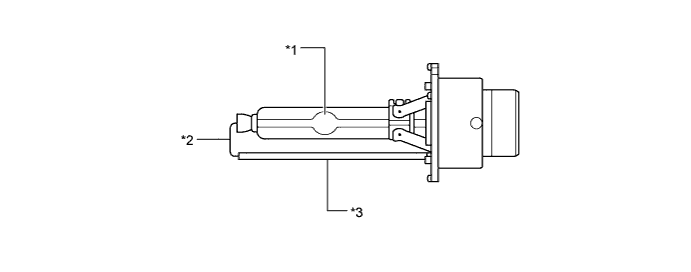
Text in Illustration *1 Arc Tube *2 Lead Wire *3 Ceramic Pipe - -
-
-
Discharge bulbs have the following advantages:
-
The light emitted by the bulb is close in color to sunlight. The light shines ahead over a broader area and further forward, increasing the area visible to the driver.
-
Less power is consumed.
-
-
-
-
OPERATION
-
Bi-function
-
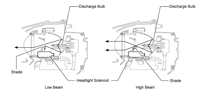
If the low beam is selected, the lower illumination area of the discharge bulb is blocked by a shade and only the upper illumination area is used.
-
If the high beam is selected, the headlight solenoid rotate the shade down to allow use of the lower illumination area, thus increasing the illumination area and improving visibility when the high beam is selected.
-
The bi-function is activated by the main body ECU (instrument panel junction block assembly). The main body ECU (instrument panel junction block assembly) sends a high beam activation signal and activates the built-in headlight solenoid to slide the shade down.
-
-
Lightguide Technology
-
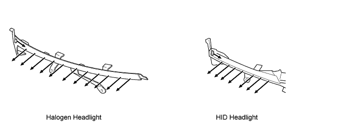
Headlight Lightguide
-
The DRL lightguides are used in the clearance lights and the daytime running lights.
-
The DRL lightguide reflects the light of the LEDs with its 'slits'.
-
-
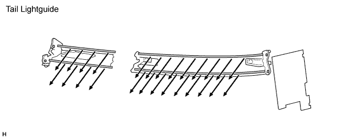
Rear Combination Light Lightguide
-
Tail lightguides have been adopted in the taillights, and stop flatguides have been adopted in the stop lights.
-
The tail lightguide reflects the light of the LEDs with two horizontal 'tubes'.
-
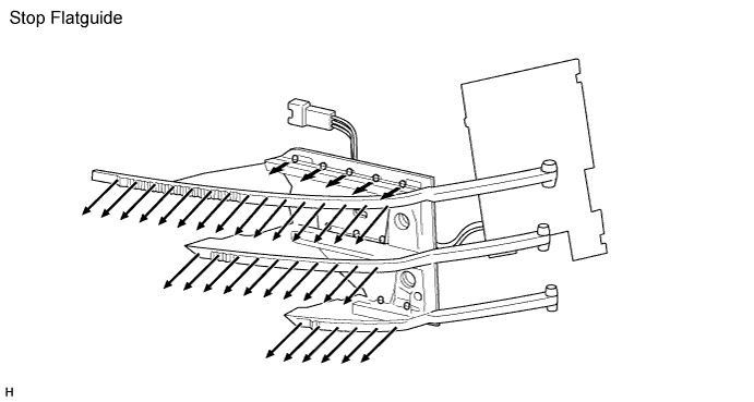
The stop flatguide expands the light of the LEDs with three horizontal 'bars'.
-
-
-
Emergency Brake Signal
-
The operating and ending conditions for the emergency brake signal are listed below. When the emergency brake signal operates, the skid control ECU causes the stop light control relay assembly to blink the stop lights. When the emergency brake signal ends, the skid control ECU causes the stop light control relay assembly to end the blinking of the stop lights.
Emergency Brake Signal Operating Condition Activates when all of the following conditions are satisfied:
-
The vehicle speed is 55 km/h (34 mph) or more.
-
The system judges from a depression of the brake pedal and a drop in vehicle speed that emergency braking is occurring.
Emergency Brake Signal Ending Condition Stops the operation when any of the following conditions is met:
-
The system judges from the vehicle's deceleration that no emergency braking is occurring.
-
The hazard warning light is blinking.
-
The brake pedal is released.
-
-
-
-
FAIL-SAFE
-
HID Headlight System
-
The light control ECU executes the fail-safe actions listed below in accordance with the problem that has been detected:
Problem Outline Detection of Abnormal Input Voltage If the voltage input to the light control ECU deviates from the normal operating voltage (10 V to 16 V), the light control ECU stops illuminating the headlights. It resumes illuminating the headlights once the voltage reverts to the operating voltage range. However, if the input voltage decreases after the headlights have illuminated, the headlights will remain illuminated until the input voltage is insufficient to light the bulbs. Detection of Abnormal Output (Open Circuit or Short Circuit) If an abnormal condition (open or short) occurs in the voltage that is output by light control ECU, the light control ECU stops illuminating the headlights and will maintain this state until the power is reinstated. Power is reinstated by turning the light control switch from off to on. Detection of Bulb Open If a bulb has not been inserted into the socket, the light control ECU stops producing a high voltage 1 second after the power has been turned on. The light control ECU will maintain this state until a bulb is correctly inserted and the power is reinstated by turning the light control switch from off to on.
-
-
Automatic Headlight Beam Level Control System
-
If the headlight swivel ECU assembly detects a malfunction in the automatic headlight beam level control system or intelligent AFS, it will take the actions indicated in the table below:
Trouble Area Condition (Fail-safe Control for Automatic Headlight Beam Level Control) AFS OFF Indicator Light Headlight Swivel Motor Malfunction Continues to control until a position of 0.65° less than the current position is reached. Blinks Steering Angle Sensor Signal Malfunction Continues to control. Blinks Speed Sensor Signal Malfunction -
Continues to control using the normal speed sensor signal if one signal fails.
-
Judges that the vehicle speed is 0 km/h (0 mph) and continues to control if both speed sensor signals fail.
Blinks Height Control Sensor Signal Malfunction -
Stops the operation after returning to initial position (fails at higher than initial position).
-
Stops the operation in current condition (fail at lower than initial position).
Blinks Headlight Leveling Motor Malfunction Normal Side Headlight Leveling Motor:
-
Stops the operation after returning to initial position (fails at higher than initial position).
-
Stops in current condition (fails at lower than initial position).
Blinks Abnormal Side Headlight Leveling Motor:
-
Stops in its current position.
Blinks Communication Signal Malfunction Skid Control ECU:
-
Judges that the vehicle speed is 0 km/h (0 mph) and continues to control.
Blinks Steering Angle Sensor:
-
Controls the system normally.
Blinks -
-
-
Intelligent AFS
-
If the headlight swivel ECU assembly detects a malfunction in the intelligent AFS or automatic headlight beam level control system, it will take the actions indicated in the table below:
Trouble Area Condition (Fail-safe Control for Intelligent AFS) AFS OFF Indicator Light Headlight Swivel Motor Malfunction Normal Side Headlight Swivel Motor:
-
Stops operating after returning to the initial position.
Blinks Abnormal Side Headlight Swivel Motor:
-
Stops in its current position.
Blinks Steering Angle Sensor Signal Malfunction Stops operating after returning to the initial position. Blinks Speed Sensor Signal Malfunction Stops operating after returning to the initial position. Blinks Height Control Sensor Signal Malfunction Stops operating after returning to the initial position. Blinks Headlight Leveling
Motor Malfunction
Stops operating after returning to the initial position. Blinks Communication Signal
Malfunction
Main Body ECU (Instrument Panel Junction Block Assembly):
-
Stops operating after returning to the initial position.
Blinks ECM:
-
Stops operating after returning to the initial position.
Blinks Skid Control ECU:
-
Stops operating after returning to the initial position.
Blinks Steering Angle Sensor:
-
Stops operating after returning to the initial position.
Blinks -
-
-
-
DIAGNOSIS
-
Automatic Headlight Beam Level Control System
-
If the headlight swivel ECU assembly detects a malfunction in the automatic headlight beam level control system, the headlight swivel ECU assembly blinks the AFS OFF indicator light. At the same time, the Diagnostic Trouble Codes (DTCs) are stored in memory. The DTCs can be read by use of the intelligent tester II. For details, refer to the AVENSIS Repair Manual.
-
-
Intelligent AFS
-
If the headlight swivel ECU assembly detects a malfunction in the intelligent AFS, the headlight swivel ECU assembly blinks the AFS OFF indicator light in order to alert the driver. At the same time, the DTCs are stored in the memory. The DTCs can be read by using the intelligent tester II. For details, refer to the AVENSIS Repair Manual.
-
-