MONITOR SYSTEM DETAILS
-
FUNCTION OF MAIN COMPONENTS
Component Function Rear Television Camera Assembly Captures the view behind the vehicle and transmits the image to the navigation receiver assembly. Navigation Receiver Assembly -
Receives signals from the back-up light switch assembly or park/neutral position switch assembly and turns the rear television camera assembly on and off.
-
Displays the image transmitted by the rear television camera assembly on the screen.
Back-up Light Switch Assembly*1 Transmits the on/off signal of the back-up light switch assembly to the navigation receiver assembly. Park/Neutral Position Switch Assembly*2 Transmits the R position signal to the navigation receiver assembly. -
*1: Models with manual transaxle
-
*2: Models with automatic transaxle
-
-
OPERATING CONDITION
-
The monitor system operates when all the following conditions have been met:
-
The ignition switch (engine switch*) is ON.
-
Shift lever is in R.
-
*: Models with entry and start system
-
-
-
-
FUNCTION
-
Area Displayed on Screen
-
On the display, objects on the right of the vehicle appear on the right side of the display panel, and objects on the left of the vehicle appear on the left side of the display panel.
-
The rear television camera assembly uses a wide-angle lens. The perceived distance from images that appear on the screen differs from the actual distance.
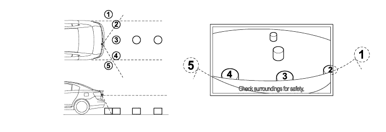
Tech Tips
The area displayed on screen may vary according to vehicle status or road conditions. The area covered by the rear television camera assembly is limited. The rear television camera assembly does not show objects close to either corner of the bumper or the area under the bumper.
-
-
-
FAIL-SAFE
-
The table below indicates the conditions of detecting malfunctions in this system:
Malfunctioning Part Detection Item Function Rear Television Camera Assembly Transmission of rear television camera assembly malfunction signal. Stops signal reception and displays a dark screen.
-
-
DIAGNOSIS
-
The monitor system is equipped with a diagnosis function which can display the diagnosis menus. For details, refer to the AVENSIS Repair Manual.
-