DYNAMIC RADAR CRUISE CONTROL SYSTEM DETAILS
-
FUNCTION OF MAIN COMPONENTS
Component Function Cruise Control Switch Main Switch Turns on/off the power to the dynamic radar cruise control system. MODE Switch Switches the control mode, between the constant speed control mode and vehicle-to-vehicle distance control mode. CANCEL Switch A cancel signal can be output to the ECM through the operation of this switch. RES/+ Switch The acceleration function and resume control function can be performed by operating this switch. A signal is output to the ECM when this switch is operated. SET/- Switch The deceleration function and set control function can be performed by operating this switch. A signal is output to the ECM when this switch is operated. Distance Control Switch While the system is in the vehicle-to-vehicle distance control mode, the driver can operate the distance control switch to select the vehicle-to-vehicle distance in 3 stages: long, middle, and short. Windshield Wiper Switch Assembly Transmits a windshield wiper switch signal to the driving support ECU. Stop Light Switch Assembly Detects the depressing of the brake pedal and transmits a signal to the ECM. Millimeter Wave Radar Sensor Radiates millimeter waves forward, uses the reflected millimeter waves for detecting the presence of a vehicle being driven ahead, the vehicle-to-vehicle distance, and the relative speed, and transmits these pieces of information to the driving support ECU. Steering Angle Sensor Detects the angle and direction of steering and transmits signals to the skid control ECU and driving support ECU. Yaw Rate Sensor Detects the yaw rate of the vehicle and transmits signals to skid control ECU and driving support ECU. Speed Sensor Detects the vehicle speed and transmits a signal via the skid control ECU to the combination meter assembly. Injector Adjusts the fuel injection volume based on the signals from the injector driver. Combination Meter Assembly Cruise Main Indicator Light -
Illuminates when the constant speed control mode is on.
-
If the ECM detects a malfunction, this light blinks to warn the driver.
Radar Cruise Indicator Light -
Illuminates when the vehicle-to-vehicle distance control mode is on.
-
If the ECM detects a malfunction, this light blinks to warn the driver.
Cruise SET Indicator Light Illuminates when the constant speed control mode or the vehicle-to-vehicle distance control mode is set. Multi-information Display During the vehicle-to-vehicle distance control, the multi-information display receives signals from the driving support ECU, in order to display the system conditions. Master Warning Light Illuminates when there is a malfunction in the system. Multi Buzzer If the ECM and driving support ECU detect automatic cancel or warning signals while the vehicle is operating under cruise control, the multi buzzer sounds to inform the driver. Driving Support ECU While the system is in the vehicle-to-vehicle distance control mode, the driving support ECU detects the vehicle being followed based on signals from the millimeter wave radar sensor. Then, the driving support ECU calculates the acceleration or deceleration rate required in order to attain the target vehicle-to-vehicle distance, and outputs a request signal to the ECM and/or skid control ECU. ECM -
Controls the constant speed control mode in accordance with signals from the switches and sensors.
-
If the ECM detects a malfunction in the dynamic radar cruise control system, it will store a Diagnostic Trouble Code (DTC).
Injector Driver Receives signals from the ECM to control the injector. Skid Control ECU While the system is operating in vehicle-to-vehicle distance control mode, the skid control ECU actuates the brake actuator in accordance with the brake request signal received from the driving support ECU. In addition, the ECU transmits signals such as a wheel speed and estimated vehicle acceleration speed to the driving support ECU. Brake Actuator Assembly Actuates the brakes in accordance with the signals from the skid control ECU. -
-
FUNCTION
-
Control of Dynamic Radar Cruise Control System Varies Depending on Mode
-
A: Constant speed control mode
-
B: Vehicle-to-vehicle distance control mode
Function Outline Mode A B Constant Speed Control The ECM compares the actual vehicle speed and the set speed and if the vehicle speed is higher than the set speed, the ECM decreases the fuel injection volume by regulating the 4 injectors via the injector driver. If the actual vehicle speed is lower than the set speed, the ECM increases the fuel injection volume by regulating the 4 injectors via the injector driver. ○ ○ Deceleration Control Effects fuel injection volume control and brake control in order to decelerate the vehicle so that the vehicle-to-vehicle distance between the vehicle and the vehicle ahead equals the set distance. - ○ Follow-up Control After effecting deceleration control, the vehicle follows the vehicle ahead in order to maintain the proper vehicle-to-vehicle distance in accordance with the vehicle speed. - ○ Acceleration Control Accelerates the vehicle in order to attain the set vehicle speed if the vehicle or the vehicle ahead has changed lanes. - ○ Set Control While this system fulfils the following conditions, and the cruise control switch is pressed to the SET/- direction and released when the main switch on the cruise control switch has been pressed to turn the system on, the ECM stores the vehicle speed and maintains the vehicle constantly at that speed.
-
The shift lever is in D.
○ ○ The vehicle is running within the following speed range:
-
Approx. 50km/h to 200 km/h (30 mph to 125 mph)
○ - The vehicle is running within the following speed range:
-
Approx. 50km/h to 170 km/h (30 mph to 105 mph)
- ○ Low Speed Limit Control The low speed limit is the lowest speed that dynamic radar cruise control system can be set at and it is designed to be approx. 40 km/h (25 mph). The dynamic radar cruise control system cannot be set below this speed. If the vehicle speed drops below this speed while running in the dynamic radar cruise control system, the dynamic radar cruise control system will be canceled automatically. However, the set speed is kept in the memory. ○ ○ Coast Control While the cruise control switch is held to the SET/- direction, the vehicle speed and the set speed change as follows, in accordance with the mode: ○ ○ -
The vehicle decelerates constantly.
-
The set speed changes to the speed at which the switch was turned off.
○ - -
The set speed decreases in increments of 5 km/h or 5 mph (example: 57 → 55 → 50 km/h, 57 → 55 → 50 mph).
-
The vehicle decelerates rapidly due to the ECD system.
- ○ Tap-down Control When the cruise control switch is pushed momentarily (approx. 0.6 seconds) to the SET/- direction, the vehicle speed and the set speed change as follows, in accordance with the mode:
-
The vehicle will decelerate in increments of approx. 1.6 km/h (1 mph) each time the switch is pressed.
-
However, if the difference between the actual vehicle speed and the set speed is greater than 5 km/h (3 mph), the set speed will change to the speed at which the vehicle was being driven at the time the switch was operated.
○ - When the cruise control switch is pushed momentarily (approx. 0.6 seconds) to the SET/- direction, the vehicle will decelerate in increments of approx. 5 km/h or 5 mph for each time the switch is pressed. - ○ Accelerator Control When the cruise control switch is pushed to the RES/+ direction and held, the vehicle speed and the set speed change as follows, in accordance with the mode: ○ ○ -
The vehicle will accelerate constantly.
-
The set speed changes to the speed at which the switch was turned off.
○ - -
The set speed increases in increments of 5 km/h or 5 mph (example: 52 → 55 → 60 km/h, 52 → 55 → 60 mph)
-
The vehicle will accelerate to the speed that is set at the time the switch is released.
-
However, only the set speed will change during follow-up control.
- ○ Tap-up Control When the cruise control switch is pushed momentarily (approx. 0.6 seconds) to the RES/+ direction, the vehicle speed and the set speed change as follows:
-
The vehicle will accelerate in increments of approx. 1.6 km/h (1 mph) each time the switch is pressed.
-
However, if the difference between the actual vehicle speed and the set speed is greater than 5 km/h (3 mph), the set speed does not change.
○ - When the cruise control switch is pushed momentarily (approx. 0.6 seconds) to the RES/+ direction, the vehicle will accelerate in increments of approx. 5 km/h or 5 mph for each time the switch is pressed. - ○ Resume Control -
When the driver pushes the cruise control switch to the RES/+ direction after the vehicle speed has exceeded the low speed limit, the dynamic radar cruise control system resumes operation to reach the vehicle speed that was set at the time the driver canceled the dynamic radar cruise control system.
-
Even if the vehicle speed drops below the low speed limit, resume can be performed when the vehicle speed exceeds the low speed limit.
○ ○ If the vehicle ahead changes driving lanes during follow-up control, the vehicle speed is gradually increased to the set speed. At this time, the vehicle speed can be increased promptly by pushing the cruise control switch to the RES/+ direction. - ○ Shift Down Control When the vehicle is traveling uphill using cruise control, automatic transaxle control may cause the transaxle to shift down. During shift down control, when the end of uphill travel is determined, the transaxle will shift up after a certain period of time. When the transaxle shifts down during the accelerator control or the resume control, the transaxle will shift up after the accelerator control or the resume control ends. ○ ○ Manual Cancel Control If any of the following conditions is met, the dynamic radar cruise control system will be canceled:
-
A stop light switch on signal is sent to the ECM (the brake pedal is depressed).
-
The shift lever is moved to any position except D.
-
A CANCEL switch on signal is sent to the ECM (the cruise control switch is moved to the CANCEL direction).
-
A main switch off signal is sent to the ECM.
-
A VSC operation signal is sent to the ECM.
○ ○ Automatic Cancel Control When an automatic cancel signal is sent to the ECM, the dynamic radar cruise control system operation is canceled. At this time, the warning method and the control resumption condition vary in accordance with the cancel signal. ○ ○ Mode Switching Control The following operations switch the modes:
-
1) Main switch on the cruise control switch is on (starts in the vehicle-to-vehicle distance control mode).
-
2) Cruise control switch is held to the MODE direction (approx. 1 second or more).
-
If the switch is pushed in any other direction before switching modes, switch the dynamic radar cruise control system off, then, perform steps 1) and 2) again.
○ ○ Diagnosis If a malfunction occurs in the dynamic radar cruise control system during the system operation, the ECM cancels dynamic radar cruise control system and diagnoses and memorizes the faults related to the malfunction. ○ ○ -
-
-
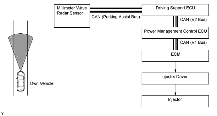
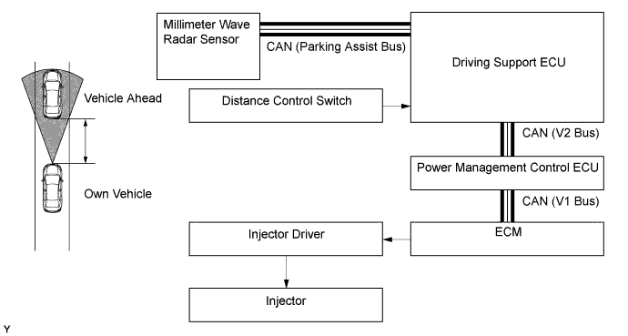
Constant Speed Control Function in Vehicle-to-vehicle Distance Control Mode
-
The millimeter wave radar sensor transmits the information about the vehicle ahead to the driving support ECU and also transmits a millimeter wave radar sensor operation signal to the ECM. The driving support ECU transmits this signal to the ECM. The ECM compares the set speed and the actual vehicle speed, and effects constant speed control by regulating the fuel injection volume in order to attain the set speed.
-
-
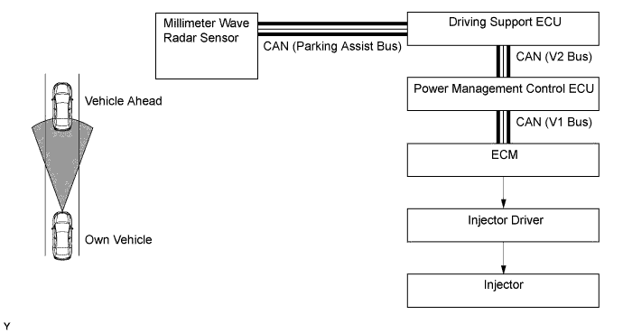
Deceleration Control Function
-
The driving support ECU calculates the target deceleration rate in accordance with signals from the millimeter wave radar sensor, and transmits a deceleration request signal to the ECM. Upon receiving this signal, the ECM decreases the fuel injection volume by regulating the 4 injectors via the injector driver in order to cause the vehicle to decelerate.
-
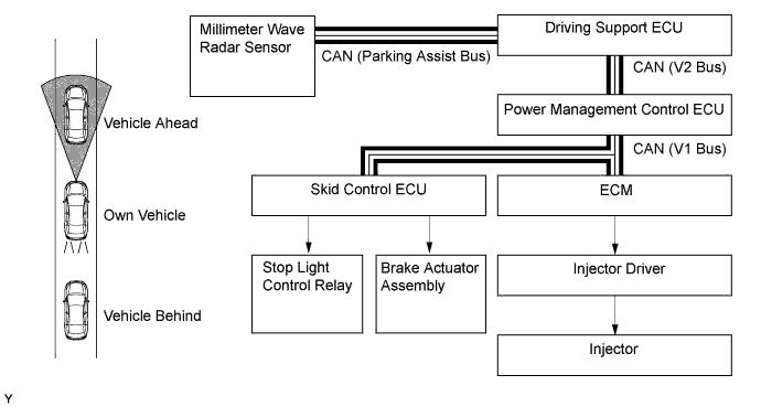
This control is not effected in the presence of a parked vehicle or object, or below the settable vehicle speed range.
-
If the driving support ECU determines that further deceleration is necessary, it transmits a brake request signal to the ECM. Upon receiving this signal, the ECM transmits a brake request signal to the skid control ECU. The skid control ECU then controls the brake actuator assembly to apply the brakes.
-
At this time, if the deceleration rate is higher than a predetermined value, the skid control ECU outputs a stop light illumination request signal to the stop light control relay, in order to inform anyone who might be following the vehicle.
-
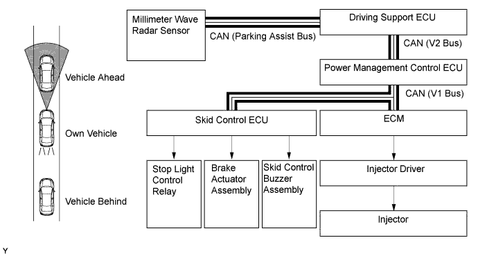
If further deceleration is necessary after the stop light is illuminated, the skid control ECU sounds the skid control buzzer assembly based on the request signal from the driving support ECU to urge the driver to depress the brake pedal.
-
-
Follow-up Control Function
-
After effecting deceleration control, the driving support ECU transmits a request signal to the ECM so that the vehicle can follow the vehicle ahead while maintaining the proper vehicle-to-vehicle distance in accordance with the vehicle speed. Upon receiving this signal, the ECM regulates the fuel injection volume in order to effect follow-up control.
-
3 stages (long, middle, and short) of vehicle-to-vehicle distance can be selected by operating the distance control switch.
-
-
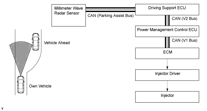
Acceleration Control Function
-
If the driving support ECU detects (based on the millimeter wave radar sensor) that either the vehicle or the vehicle ahead has changed lanes, an acceleration request signal is transmitted to the ECM in order to attain the set vehicle speed. Upon receiving this signal, the ECM regulates the fuel injection volume in order to effect acceleration control.
-
-
Automatic Cancel Control Function
-
If any of the conditions listed below occurs while the vehicle is in cruise control (A: constant speed control mode, B: vehicle-to-vehicle distance control mode), the cruise control will be canceled.
-
The following items are used as a warning on the automatic cancel control function:
-
a: Multi-information display (shows warning message)
-
b: Master warning light
-
c: Multi buzzer
-
d: Cruise main indicator light
-
e: Radar cruise indicator light
Mode Description of Malfunction Warning A and B If any of the conditions listed below occurs, the ECM clears the set speed and cancels the cruise control:
-
Malfunction of the vehicle speed signal.
-
An open or short circuit in the stop light switch.
The cruise control is prohibited until the conditions are restored or the dynamic radar cruise control system is turned off and back on again using the main switch on the cruise control switch.
a: "CHECK CRUISE CONTROL SYSTEM"
b: Illuminates
c: Sounds once
d: Blinks (in the case of A)
e: Blinks (in the case of B)
If the condition below occurs, the ECM clears the set speed and cancels the cruise control:
-
The ECD system has a malfunction.
The cruise control is prohibited until the conditions are restored or the dynamic radar cruise control system is turned off and back on again using the main switch on the cruise control switch.
a: -
b: -
c: -
d: -
e: -
If the condition below occurs, the ECM cancels the cruise control while retaining the set speed in its memory:
-
The vehicle speed drops below low speed limit (approx. 40 km/h [25 mph]).
a: -
b: -
c: Sounds once
d: -
e: -
A If the condition below occurs, the ECM cancels the cruise control:
-
The vehicle speed drops more than 16 km/h (10 mph) below the set speed.
a: -
b: -
c: -
d: -
e: -
B If any of the conditions listed below occurs, the ECM clears the set speed and cancels the cruise control:
-
Malfunction of the millimeter wave radar sensor.
-
Displacement of the axis of the millimeter wave radar sensor.
-
Malfunction in the dynamic radar cruise control system other than those given above.
The cruise control is prohibited until the ignition switch (engine switch*) is turned ON again.
a: "CHECK CRUISE CONTROL SYSTEM"
b: Illuminates
c: Sounds once
d: -
e: Blinks
If the condition below occurs, the ECM cancels the cruise control while retaining the set speed in its memory:
-
The millimeter wave radar sensor is dirty.
The cruise control is prohibited until the conditions are restored or the main switch on the cruise control switch is turned on again.
a: "CLEAN RADAR SENSOR"
b: Illuminates
c: Sounds once
d: -
e: Blinks
If any of the conditions listed below occurs, the ECM cancels the cruise control while retaining the set vehicle speed in its memory:
-
The wipers operate at high speed (including AUTO mode).
-
The measurement becomes extremely unstable due to poor weather conditions.
The cruise control is prohibited until the conditions are remedied or the dynamic radar cruise control system is turned off and back on again using the main switch on the cruise control switch.
a: "CRUISE CONTROL NOT AVAILABLE"
b: Illuminates
c: Sounds once
d: -
e: Blinks
-
-
*: Models with entry and start system
-
-
-
-
CONSTRUCTION
-
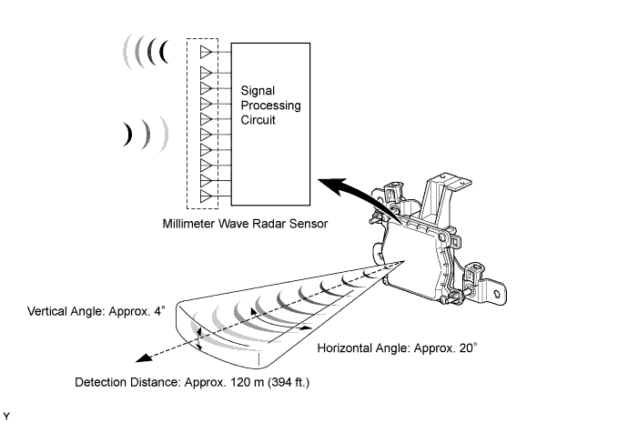
Millimeter Wave Radar Sensor
-
The millimeter wave radar sensor consists of a millimeter wave radar circuit, signal processing circuit, and CPU.
-
The millimeter wave radar circuit consists of one transmission antenna and nine reception antennas.
-
The millimeter wave radar sensor outputs millimeter waves when the vehicle speed is above 0 km/h (0 mph), and does not when the vehicle speed is at 0 km/h (0 mph). The millimeter wave radar sensor uses frequencies in the 76 GHz band.
-
The reception antennas receive the millimeter waves that have been reflected.
-
The signal processing circuit detects the distance, relative speed, and the direction of the object by generating millimeter waves and calculating the signals received by the reception antennas. Then, it transmits this information to the driving support ECU.
Tech Tips
When either the driving support ECU or the ECM is replaced, the millimeter wave radar sensor information stored in the replaced ECU must be initialized. For details, refer to the AVENSIS Repair Manual.
Tech Tips
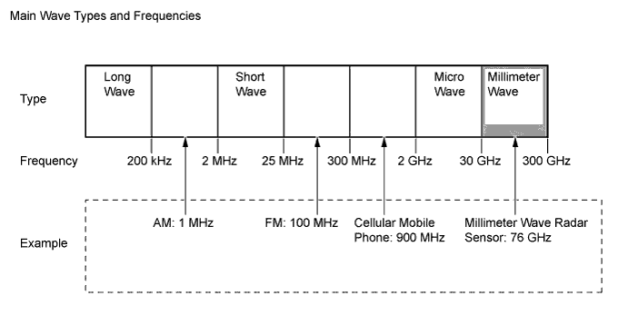
Millimeter Wave Radar:
The millimeter wave radar uses an extremely high frequency band between 30 GHz and 300 GHz, with an extremely short wavelength between 1 mm and 10 mm (0.04 in. and 0.40 in.) in a vacuum. The millimeter wave radar sensor uses frequencies in the 76 GHz band. The millimeter wave radar is less affected by weather conditions such as rain, fog, or snow, and provides excellent characteristics for recognizing objects.
-
Calculation Method
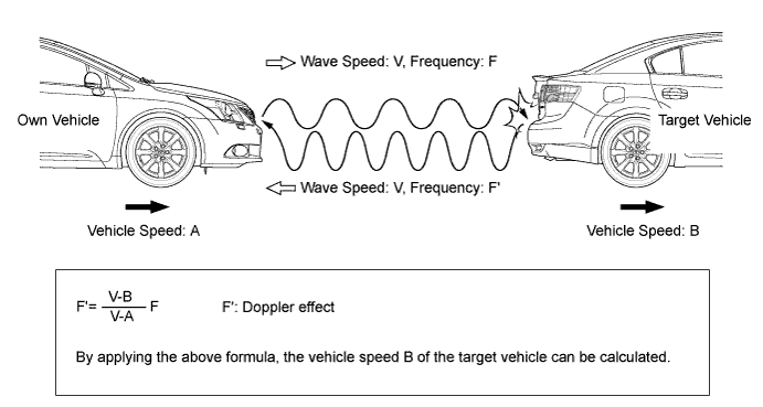
The distance to the object, azimuth (horizontal angle), and relative speed are calculated from the information provided by reflected millimeter waves as described below:
Distance Calculated based on the length of time between emission and reception of millimeter waves by the millimeter wave radar sensor. Azimuth Calculated based on the angle of the millimeter wave reflected by an object. Relative Speed Calculated by utilizing the changes (Doppler effect) that occur in the frequencies of the reflected millimeter waves. Tech Tips
The Doppler effect causes the observer to perceive the radio waves emitted by a moving object to be at higher frequencies as it approaches, and to be at lower frequencies as it recedes. This phenomenon occurs because when an object is located far away, the radio waves are perceived to be at higher frequencies than when it is at the radio source.
Tech Tips
After a millimeter wave radar sensor has been replaced or removed and reinstalled, the intelligent tester II must be used to adjust the sensor angle. To ensure the proper precision, the sensor must be adjusted in the horizontal and vertical state. For this reason, the sensor is provided with an area for placing at a level, as well as a horizontal adjusting screw and a vertical adjusting screw. For details, refer to the AVENSIS Repair Manual.
-
-
Cruise Control Switch
-
The cruise control switch consists of the main, RES/+, SET/-, MODE and CANCEL switches. The RES/+, SET/-, MODE and CANCEL switches are a lever that operates in 4 directions.
-
The cruise control switch is an automatic reset (normally open) type that turns on only when the switch is being operated and turns off as soon as the driver releases the switch. Furthermore, the functions of the control switch are active only when the dynamic radar cruise control system has been turned on.
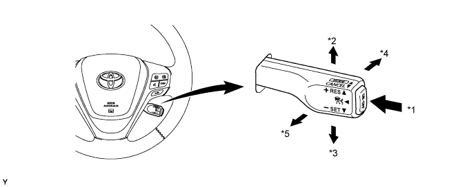
Text in Illustration *1 Main Switch *2 RES/+ *3 SET/- *4 MODE *5 CANCEL - -
-
-
Distance Control Switch
-
While the vehicle is being driven in vehicle-to-vehicle distance control mode, the vehicle-to-vehicle distance setting can be changed each time the distance control switch is pressed, as follows:
Mode Vehicle-to-vehicle Distance* Long Approx. 50 m (160 ft.) Middle Approx. 40 m (130 ft.) Short Approx. 30 m (100 ft.) Tech Tips
*: While driving at a vehicle speed of 80 km/h (50 mph).
-
If the ignition switch (engine switch*) is turned off and back to ON, the system will be set to "long".
-
*: Models with entry and start system
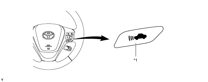
Text in Illustration *1 Distance Control Switch - - -
-
-
Combination Meter Assembly
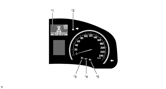
Text in Illustration *1 Multi-information Display *2 Master Warning Light *3 Cruise Main Indicator Light *4 Cruise SET Indicator Light *5 Radar Cruise Indicator Light - - -
The combination meter assembly illuminates the indicator lights or gives an indication on the multi-information display, and sounds a multi buzzer (which is built into the combination meter assembly) in accordance with the respective condition.
Mode Condition 


Multi-information Display Multi Buzzer Constant Speed Control Main Switch on and Pressed and Held in MODE Direction Illuminates - - - - - Mode Set Illuminates - Illuminates - 
- Malfunction Occurred Blinks - - Illuminates 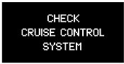
Sounds Vehicle-to-vehicle Distance Control Main Switch on - Illuminates - - 
- Constant Speed Control No Vehicle Ahead - Illuminates Illuminates - - Follow-up Control Vehicle Ahead (Long Distance) - Illuminates Illuminates - 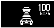
- Vehicle Ahead (Middle Distance) - Illuminates Illuminates - 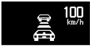
- Vehicle Ahead (Short Distance) - Illuminates Illuminates - 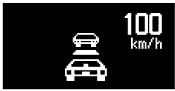
- Vehicle-to-vehicle Distance Control Deceleration Control Proximity Warning - Illuminates Illuminates - 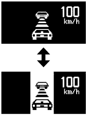
- Millimeter Wave Radar Sensor is Dirty - Blinks - Illuminates 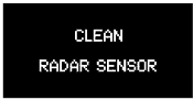
Sounds Poor Weather Conditions - Blinks - Illuminates 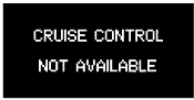
Sounds Malfunction Occurred - Blinks - Illuminates Sounds Beam Axis Adjustment - Illuminates - - 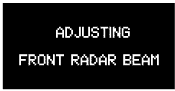
-
-
-
-
DIAGNOSIS
-
If a malfunction occurs in the dynamic radar cruise control system, the ECM cancels the dynamic radar cruise control system. The ECM blinks the cruise main indicator light or the radar cruise indicator light and displays a warning message on the multi-information display to inform the driver of the malfunction. At this time, the ECM memorizes the malfunction in the form of a 5-digit Diagnostic Trouble Code (DTC). For details of the DTC, refer to the AVENSIS Repair Manual.
-