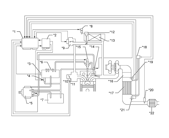
| *1 |
ECM |
*2 |
Injector Driver |
| *3 |
Fuel Pressure Sensor |
*4 |
Pressure Discharge Valve |
| *5 |
Supply Pump |
*6 |
Common-rail Assembly |
| *7 |
Fuel Tank |
*8 |
VSV for EGR Cooler |
| *9 |
EGR Valve |
*10 |
Throttle Position Sensor |
| *11 |
Diesel Throttle Control Motor |
*12 |
EGR Cooler Bypass Valve |
| *13 |
EGR Cooler |
*14 |
Exhaust Fuel Addition Injector |
| *15 |
Injector |
*16 |
Oxidation Catalytic Converter |
| *17 |
Diesel Particulate Filter (DPF) Catalytic Converter |
*18 |
Differential Pressure Sensor |
| *19 |
Exhaust Gas Temperature Sensor (Upper Side) |
*20 |
Air Fuel Ratio Sensor |
| *21 |
No. 2 Exhaust Gas Temperature Sensor (Lower Side) |
*22 |
Oxidation Catalytic Converter |