СИСТЕМА АВТОМАТИЧЕСКОЙ ТРАНСМИССИИ ДЕТАЛЬНОЕ ОПИСАНИЕ
-
FUNCTION OF MAIN COMPONENTS
Component Function Forward Clutch (C1)
Connects input shaft and front planetary sun gear. Direct Clutch (C2)
Connects intermediate shaft and rear planetary sun gear. Underdrive Clutch (C3)
Connects Underdrive sun gear and Underdrive planetary carrier. 2nd Brake (B1)
Prevents rear planetary sun gear from turning clockwise or counterclockwise. 1st and Reverse Brake (B2)
Prevents rear planetary carrier and front planetary ring gear from turning clockwise or counterclockwise. Underdrive Brake (B3)
Prevents Underdrive planetary sun gear from turning clockwise or counterclockwise. 1-way Clutch (F1)
Prevents front planetary ring gear and rear planetary carrier from turning counterclockwise. Underdrive 1-way Clutch (F2)
Prevents Underdrive planetary sun gear from turning clockwise. Planetary Gears These gears change the route through which driving force is transmitted, in accordance with the operation of each clutch and brake, in order to increase or reduce the input and output speed. Torque Converter Clutch Assembly -
Transmits the engine power to the transaxle.
-
Increases engine torque.
Oil Pump Assembly Provides oil pressure necessary for the transaxle operation. Shift Solenoid Valve SL1 -
Controls the 2nd brake (B1) pressure.
-
Controls the lock-up clutch pressure.
Shift Solenoid Valve SL2 Controls the direct clutch (C2) pressure.
Shift Solenoid Valve SLT -
Controls line pressure.
-
Controls secondary pressure.
Shift Solenoid Valve S4 Controls the 3-4 shift valve. Shift Solenoid Valve DSL -
Controls the B2control valve.
-
Controls the lock-up relay valve.
ATF Temperature Sensor Detects the ATF temperature. Speed Sensor NT Detects the input speed of the transaxle. Speed Sensor NC Detects the output speed of the transaxle. Park/Neutral Position Switch Assembly Detects the shift lever position. Transmission Control Switch -
Detects the shift lever is in S.
-
Detects the driver's shift-up and shift-down operations when the shift lever is in S.
Shift Position and Shift Range Indicator -
Indicates the shift lever position.
-
Indicates that the shift range (1st-4th) is in S.
S Mode Indicator Illuminates to inform the driver of driving in S. MIL Illuminates or blinks to inform the driver when the ECM detects a malfunction. Multi-information Display Warns the driver by displaying a message when the ATF is at a high temperature. Master Warning Light Warns the driver by lighting up when the ATF is at a high temperature. Multi Buzzer Warns the driver by sounding when the ATF is at a high temperature. ECM Controls each solenoid valve in response to a signal from each sensor and switch. -
-
SYSTEM CONTROL
-
The electronic control system of the U241E automatic transaxle consists of the controls listed below:
Control Function Clutch Pressure Control Achieves smooth shift characteristics by minutely controlling clutch pressure in accordance with engine output and driving conditions. Line Pressure Optimal Control Achieves smooth shift characteristics by minutely controlling line pressure in accordance with engine output and driving conditions. Engine Torque Control Retards the engine ignition timing temporarily to improve shift feeling during up or down shifting. Shift Control in Uphill/Downhill Traveling Achieves smooth driving by controlling shift-up and shift-down when traveling uphill or downhill. Lock-up Timing Control To effectively transmit power from the engine, controls the shift solenoid valve DSL in response to a signal from each sensor and operates the lock-up clutch. N to D Squat Control When the shift lever is moved from N to D, the gear is temporarily moved to the 2nd and then to the 1st to reduce vehicle squat. Multi-mode Automatic Transmission The ECM appropriately controls the automatic transmission in accordance with the range selected while the shift lever is in S. -
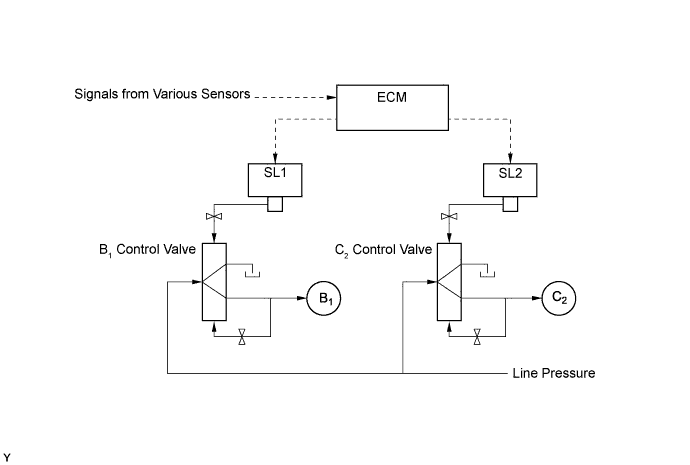
Clutch Pressure Control
-
A clutch to clutch pressure control is used for shifting from the 1st to 2nd gear, and from the 2nd to 3rd gear. Shift solenoid valves SL1 and SL2 are actuated in accordance with the signals from the ECM, and this output pressure is guided directly to the control valves B1and C2in order to regulate the line pressure that acts on the 2nd brake (B1) and direct clutch (C2). As a result, high response levels and excellent shift characteristics have been achieved.
-
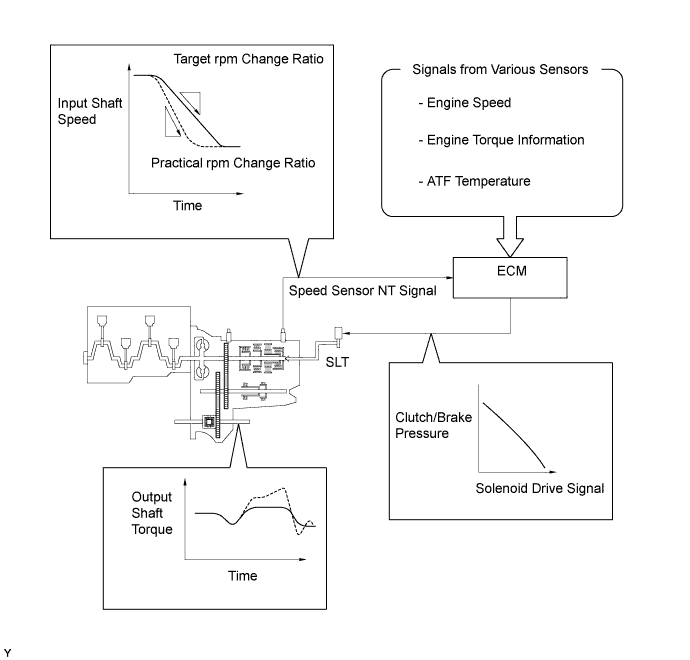
Shift solenoid valve SLT is used for optimal control of clutch pressure. The ECM monitors the signals from various sensors such as the speed sensor NT, allowing shift solenoid valve SLT to minutely control the clutch pressure in accordance with engine output and driving conditions. As a result, smooth shift characteristics have been achieved.
-
-
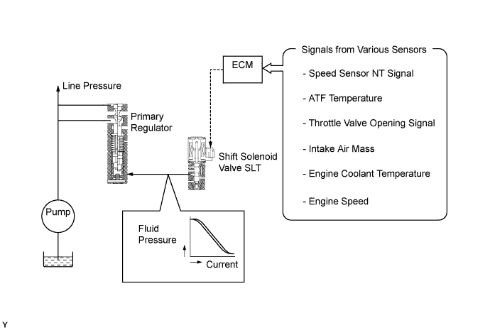
Line Pressure Optimal Control
-
Through the use of shift solenoid valve SLT, the line pressure is optimally controlled in accordance with the engine torque information, as well as with the internal operating conditions of the torque converter clutch and the transaxle. Accordingly, the line pressure can be controlled minutely in accordance with the engine output, traveling condition, and the ATF temperature, thus achieving smooth shift characteristics and optimizing the workload in the oil pump.
-
-
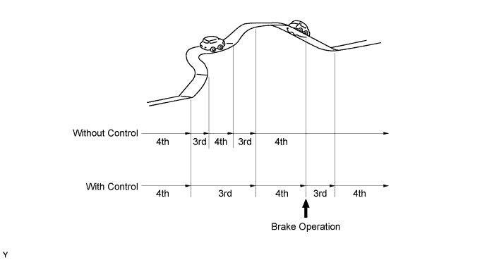
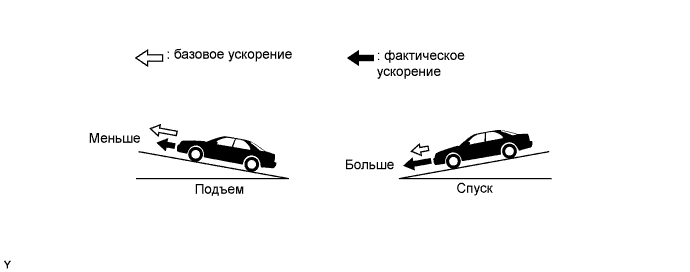
Shift Control in Uphill/Downhill Traveling
-
This control helps minimize the gear shifting when the driver operates the accelerator pedal while driving on a winding uphill or downhill road in order to ensure a smooth drive.
-
When the ECM detects uphill travel, it prohibits upshifting to the 4th after downshifting to the 3rd.
-
If a signal indicating that the driver has operated the brake pedal is input while the ECM detects downhill travel, it downshifts from the 4th to 3rd.
-
The actual acceleration calculated from the front and rear speed sensor signals is compared with the reference acceleration (based on level road travel) stored in the ECM to determine uphill or downhill travel.
-
-
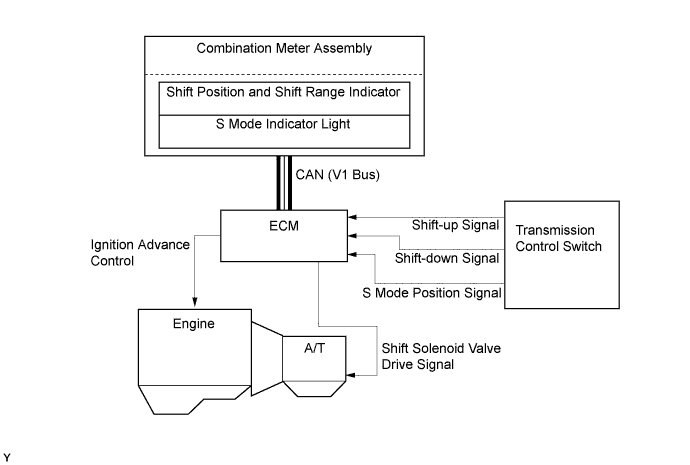
Multi-mode Automatic Transmission
-
The driver can select the desired shift range by moving the shift lever to "+" (forwards) or to "-" (backwards) while in S.
-
The multi-mode automatic transmission is designed to allow the driver to switch the gear ranges.
-
An S mode indicator which illuminates when the shift lever is in S and a shift range indicator which indicates the shift range have been provided in the combination meter.
-
The driver moves the shift lever to S. At this time, the S3 range is selected . Then, the shift range changes sequentially, as the driver moves the shift lever to "+" (forwards) or to "-" (backwards).
-
Under this control, the ECM effects optimal shift control within the usable gear range that the driver has selected. As with an ordinary automatic transmission, the ECM shifts to the 1st gear when the vehicle is stopped.
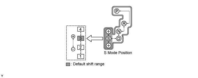
Usable Gear Chart Shift Range Indicator Shift Range Usable Gear 4 4 4th ←→ 3rd ←→ 2nd ←→ 1st 3 3 3rd ←→ 2nd ←→ 1st 2 2 2nd ←→ 1st 1 1 1st
-
-
-
FUNCTION
-
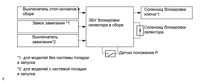
Shift Lock System
-
On the models without the entry and start system, the key interlock device prevents the key from being pulled out after the ignition switch has been turned off, unless the shift lever has been moved to P. Thus, the driver is urged to park the vehicle with the shift lever in P.
-
The shift lock mechanism prevents the shift lever from being moved to a position other than P, unless the ignition switch*1 is ON or the engine switch*2 is turned to on (IG), and the brake pedal is depressed. This prevents the vehicle from starting off suddenly.
-
The shift lock ECU uses the P detection switch to detect the shift lever position, and receives input signals from the stop light switch assembly and ignition switch*1 or engine switch*2. Upon receiving these signals, the shift lock control ECU sub-assembly turns on the key interlock solenoid*1 and the shift lock solenoid in order to release the key interlock and shift lock.
-
A shift lock release button, which manually overrides the shift lock mechanism, is used.
-
*1: Models without entry and start system
-
*2: Models with entry and start system
-
-
-
-
CONSTRUCTION
-
Torque Converter Clutch Assembly
-
This torque converter clutch has optimally designed fluid passages and impeller configuration, resulting in substantially enhanced transmission efficiency to ensure good starting, acceleration and fuel economy.
-
Furthermore, a hydraulically operated lock-up mechanism which cuts power transmission losses due to slippage at medium and high speeds is used.
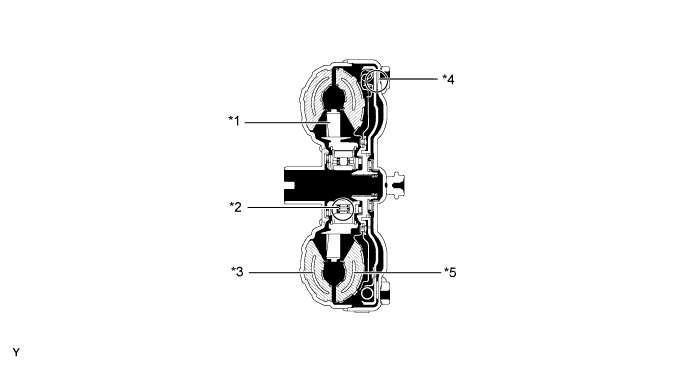
Text in Illustration *1 Stator *2 1-way Clutch *3 Pump Impeller *4 Lock-up Clutch *5 Turbine Runner - -
-
-
Oil Pump Assembly
-
The oil pump assembly is combined with the torque converter clutch. It lubricates the planetary gear units and supplies operating pressure to the hydraulic control.
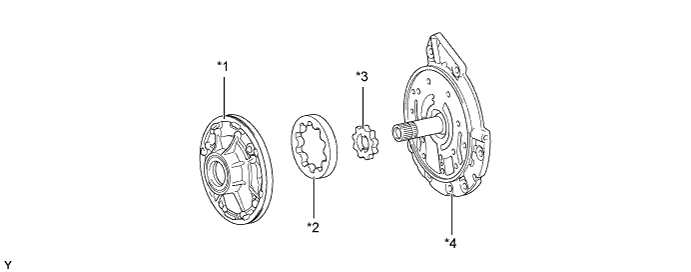
Text in Illustration *1 Oil Pump Body *2 Front Oil Pump Driven Gear *3 Front Oil Pump Drive Gear *4 Stator Shaft Assembly
-
-
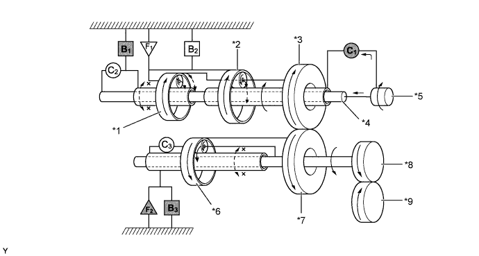
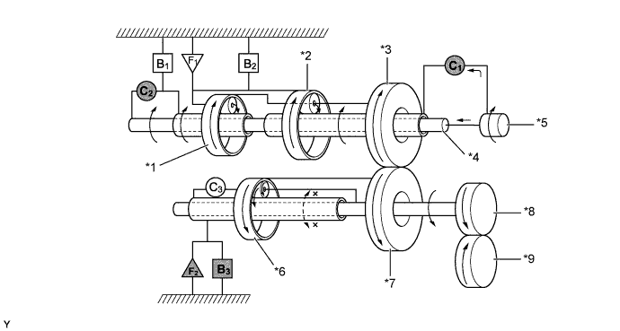
Planetary Gear Unit
-
The counter drive and driven gears are placed in front of the front planetary gear and the underdrive planetary gear unit is placed above the counter shaft. Furthermore, the number of brakes and 1-way clutches has been minimized to achieve a compact and high-capacity structure.
-
A centrifugal fluid pressure canceling mechanism is used in the direct clutch (C2) and underdrive clutch (C3) that are applied when shifting from 2nd to 3rd and from 3rd to 4th.
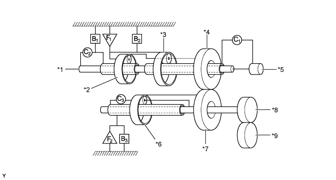
Text in Illustration C1
Forward Clutch C2
Direct Clutch C3
Underdrive Clutch B1
2nd Brake B2
1st and Reverse Brake B3
Underdrive Brake F1
1-way Clutch F2
Underdrive 1-way Clutch *1 Intermediate Shaft *2 Rear Planetary Gear *3 Front Planetary Gear *4 Counter Drive Gear *5 Input Shaft *6 Underdrive Planetary Gear *7 Counter Driven Gear *8 Differential Drive Pinion *9 Ring Gear - -
-
-
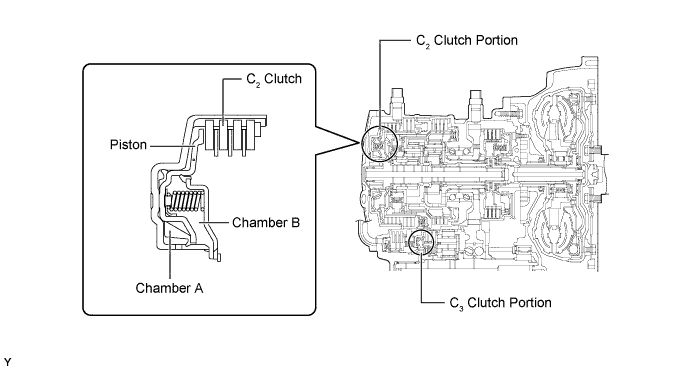
Centrifugal Fluid Pressure Canceling Mechanism
-
For the following reason, the centrifugal fluid pressure canceling mechanism is used on the direct clutch (C2) and underdrive clutch (C3):
-
Clutch shifting operation is affected not only by the valve body controlling fluid pressure but also by the centrifugal fluid pressure that is present due to the fluid in the clutch piston oil pressure chamber. The centrifugal fluid pressure canceling mechanism uses chamber B to reduce the effect applied to chamber A. As a result, smooth shifting with excellent response has been achieved.
-
-
Valve Body Unit
-
The valve body consists of the upper and lower valve bodies and 5 shift solenoid valves.
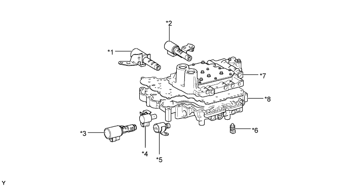
Text in Illustration *1 Shift Solenoid Valve SL1 *2 Shift Solenoid Valve SLT *3 Shift Solenoid Valve SL2 *4 Shift Solenoid Valve DSL *5 Shift Solenoid Valve S4 *6 ATF Temperature Sensor *7 Upper Valve Body *8 Lower Valve Body 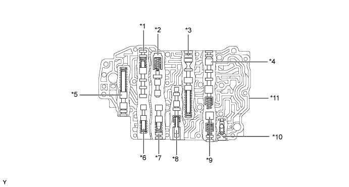
Text in Illustration *1 Lock-up Relay Valve *2 Lock-up Control Valve *3 2nd Regulator Valve *4 C2Lock Valve
*5 Solenoid Modulator Valve *6 B3Orifice Control Valve
*7 B1Lock Valve
*8 Clutch Apply Control Valve *9 C2Exhaust Check Valve
*10 3-way Check Valve *11 Upper Valve Body - - 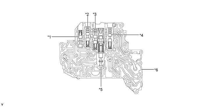
Text in Illustration *1 3-4 Shift Valve *2 B1Control Valve
*3 B2Control Valve
*4 C2Control Valve
*5 Primary Regulator Valve *6 Lower Valve Body -
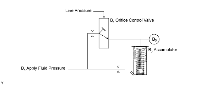
Apply orifice control, which controls the flow volume to the underdrive brake (B3), is used. This control is effected by the B3orifice control valve. The B3orifice control valve has been provided for the underdrive brake (B3), which is applied when shifting from the 4th to 3rd. The B3orifice control valve is controlled by the amount of line pressure in accordance with shifting conditions, and the flow volume of the fluid supplied to the underdrive brake (B3) is controlled by varying the size of the control valve's apply orifice.
-
-
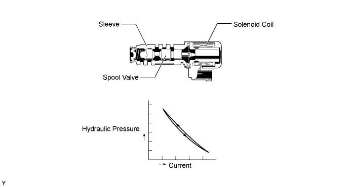
Shift Solenoid Valves SL1, SL2 and SLT
-
In order to supply hydraulic pressure proportional to the current that flows to the solenoid coil, shift solenoid valves SL1, SL2, and SLT are provided.
-
These valves linearly control the line pressure and clutch and brake engagement pressure based on the signals from the ECM.
Function of Shift Solenoid Valves SL1, SL2, and SLT Shift Solenoid Valve Function SL1 -
2nd brake (B1) pressure control
-
Lock-up clutch pressure control
SL2 Direct clutch (C2) pressure control
SLT -
Line pressure control
-
Secondary pressure control
-
-
-
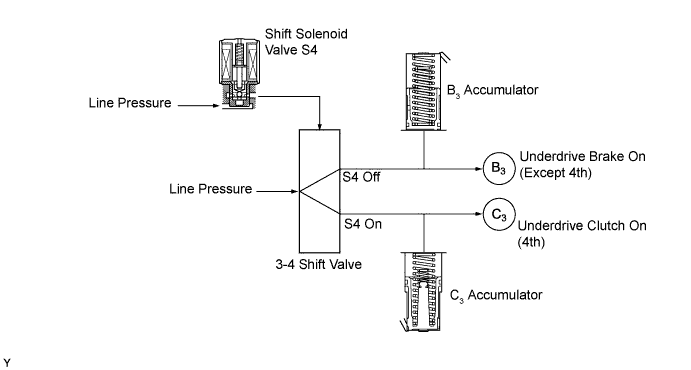
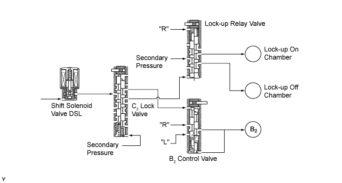
Shift Solenoid Valves S4 and DSL
-
These shift solenoid valves use a 3-way solenoid valve.
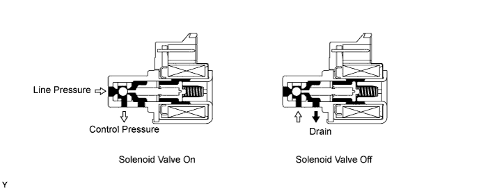
-
When set to on, shift solenoid valve S4 controls the 3-4 shift valve to establish the 4th changing over the fluid pressure applied to underdrive brake (B3) and underdrive clutch (C3).
-
Shift solenoid valve DSL controls the B2control valve via the C2lock valve when the transaxle is shifted in R or L. During lock-up, the lock-up relay valve is controlled via the C2lock valve.
-
-
ATF Temperature Sensor
-
The ATF temperature sensor is installed in the lower valve body for direct detection of the fluid temperature.
-
The ATF temperature sensor is used for correction of clutch and brake pressure to ensure smooth shift quality every time.
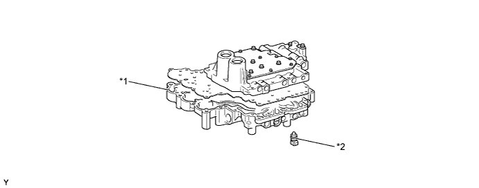
Text in Illustration *1 Lower Valve Body *2 ATF Temperature Sensor
-
-
Speed Sensor NT and Speed Sensor NC
-
This automatic transaxle uses a speed sensor NT and a speed sensor NC. Thus, the ECM can detect the timing of the shifting of the gears and appropriately control the engine torque and hydraulic pressure in response to various conditions.
-
The speed sensor NT detects the input speed of the transaxle. The direct clutch (C2) drum is used as the timing rotor for this sensor.
-
The speed sensor NC detects the speed of the counter gear. The counter drive gear is used as the timing rotor for this sensor.
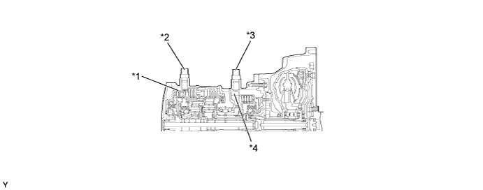
Text in Illustration *1 Direct Clutch Drum *2 Speed Sensor NT *3 Speed Sensor NC *4 Counter Drive Gear
-
-
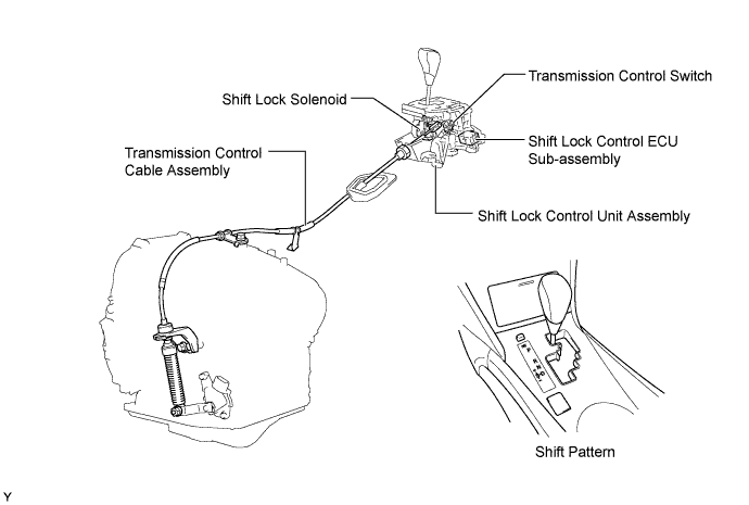
Shift Control Mechanism
-
A gate type shift lever that uses a transmission control cable is used.
-
The shift control mechanism consists of a shift lock control unit assembly and a transmission control cable assembly.
-
-
-
OPERATION
-
Transaxle Power Flow
Shift Solenoid Valve, Friction Engagement Components and 1-way Clutch Operation Shift Lever Position Solenoid Valve Friction Engagement Component 1-way Clutch SL1 SL2 S4 DSL C1
C2
C3
B1
B2
B3
F1
F2
P On On Off Off - - - - - ○ - - R On Off Off Off - ○ - - ○ ○ - - N On On Off Off - - - - - ○ - - D, S4 1st On On Off Off ○ - - - - ○ ○ ○ 2nd Off On Off Off ○ - - ○ - ○ - ○ 3rd Off Off Off Off/On* ○ ○ - - - ○ - ○ 4th Off Off On Off/On* ○ ○ ○ - - - - - S3 1st On On Off Off ○ - - - - ○ ○ ○ 2nd Off On Off Off ○ - - ○ - ○ - ○ 3rd Off Off Off Off/On* ○ ○ - - - ○ - ○ S2 1st On On Off Off ○ - - - - ○ ○ ○ 2nd Off On Off Off ○ - - ○ - ○ - ○ S1 1st On On Off On ○ - - - ○ ○ ○ ○ Tech Tips
○: Operation
-: Not operation
*: Lock-up on
-
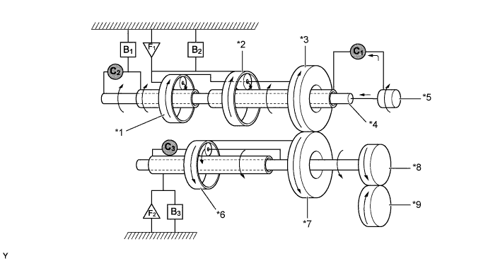
1st Gear (Shift Lever in D or S4, S3 and S2 Ranges)

Text in Illustration *1 Rear Planetary Gear *2 Front Planetary Gear *3 Counter Drive Gear *4 Intermediate Shaft *5 Input Shaft *6 Underdrive Planetary Gear *7 Counter Driven Gear *8 Differential Drive Pinion *9 Front Differential Ring Gear -
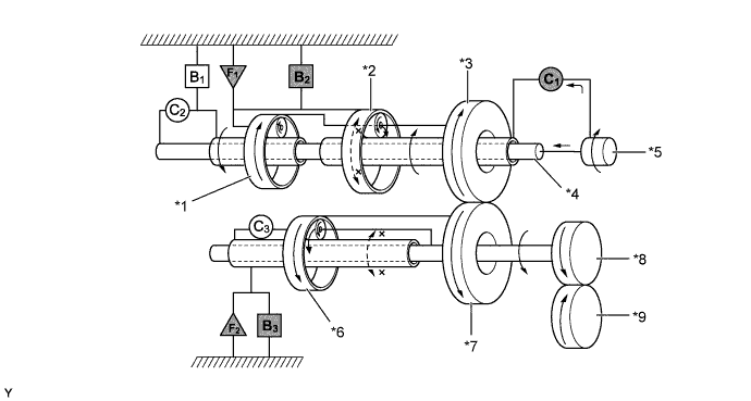
2nd Gear (Shift Lever in D or S4, S3 and S2 Ranges)
Text in Illustration *1 Rear Planetary Gear *2 Front Planetary Gear *3 Counter Drive Gear *4 Intermediate Shaft *5 Input Shaft *6 Underdrive Planetary Gear *7 Counter Driven Gear *8 Differential Drive Pinion *9 Front Differential Ring Gear -
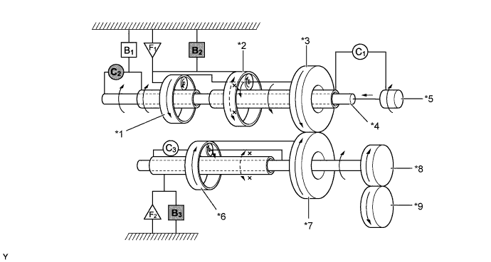
3rd Gear (Shift Lever in D or S4 and S3 Ranges)
Text in Illustration *1 Rear Planetary Gear *2 Front Planetary Gear *3 Counter Drive Gear *4 Intermediate Shaft *5 Input Shaft *6 Underdrive Planetary Gear *7 Counter Driven Gear *8 Differential Drive Pinion *9 Front Differential Ring Gear -
4th Gear (Shift Lever in D or S4 Range)
Text in Illustration *1 Rear Planetary Gear *2 Front Planetary Gear *3 Counter Drive Gear *4 Intermediate Shaft *5 Input Shaft *6 Underdrive Planetary Gear *7 Counter Driven Gear *8 Differential Drive Pinion *9 Front Differential Ring Gear -
1st Gear (Shift Lever in S1 Range)
Text in Illustration *1 Rear Planetary Gear *2 Front Planetary Gear *3 Counter Drive Gear *4 Intermediate Shaft *5 Input Shaft *6 Underdrive Planetary Gear *7 Counter Driven Gear *8 Differential Drive Pinion *9 Front Differential Ring Gear -
Reverse Gear (Shift Lever in R)
Text in Illustration *1 Rear Planetary Gear *2 Front Planetary Gear *3 Counter Drive Gear *4 Intermediate Shaft *5 Input Shaft *6 Underdrive Planetary Gear *7 Counter Driven Gear *8 Differential Drive Pinion *9 Front Differential Ring Gear
-
-
-
FAIL-SAFE
-
The fail-safe function minimizes the loss of operability when an abnormality occurs in a sensor or a shift solenoid valve.
Fail-safe Control List Malfunction Part Function Front Speed Sensors and Rear Speed Sensors During a front speed sensors and rear speed sensors malfunction, the vehicle speed is detected through the signals from the speed sensor NC to effect normal control. ATF Temperature Sensor During an ATF temperature sensor malfunction, the 4th upshift is prohibited. Speed Sensor NC During a speed sensor NC malfunction, the 4th upshift is prohibited. Shift Solenoid Valve DSL When the shift solenoid valve DSL has a malfunction, the current to the solenoid valve is stopped. This stops lock-up control, decreasing fuel economy. Shift Solenoid Valves SL1, SL2, and S4 The current to the failed shift solenoid valve is cut off and control is effected by operating the other shift solenoid valves with normal operation. For details, refer to the AVENSIS Repair Manual.
-
-
DIAGNOSIS
-
When the ECM detects a malfunction, the ECM makes a diagnosis and memorizes the failed section. Furthermore, the check engine warning light in the combination meter illuminates or blinks to inform the driver.
-
At the same time, the Diagnostic Trouble Codes (DTCs) are stored in memory. The DTCs can be read by connecting an intelligent tester II. For details, refer to the AVENSIS Repair Manual.
-