ROOF SUNSHADE SYSTEM DETAILS
-
FUNCTION OF MAIN COMPONENTS
-
Roof Sunshade System
-
The roof sunshade system consists of the following parts:
Component Function Roof Sunshade Switch The driver can operate this switch to open and close the roof sunshade. Sliding Roof Control ECU Controls the roof sunshade system by transmitting and receiving the signals of the switches and motors. Sliding Roof Drive Gear Sub-assembly Opens and closes the roof sunshade in accordance with the signals from the sliding roof control ECU. Power Management Control ECU Receives signals from the engine start switch* and inputs them into the sliding roof control ECU. Main Body ECU Receives signals from the engine start switch* via the power management control ECU and inputs them into the sliding roof control ECU. Hall IC The Hall IC converts the changes in the magnetic flux that occur due to the rotation of the worm gear into pulse signals and outputs them to the ECU. -
*: Models with entry and start system
-
-
-
-
FUNCTION
-
Roof Sunshade System
-
Roof sunshade system has following functions:
Function Outline Manual Open-and-close This function causes the roof sunshade to open or close while the roof sunshade switch is being operated. The roof sunshade stops as soon as the switch is released. One-touch Auto Open-and-close This function operates when the roof sunshade switch is pressed and held for approximately 0.3 seconds or more. Jam Protection The jam protection function automatically stops the roof sunshade and moves it open halfway if a foreign object gets jammed in the roof sunshade during close operation.
-
-
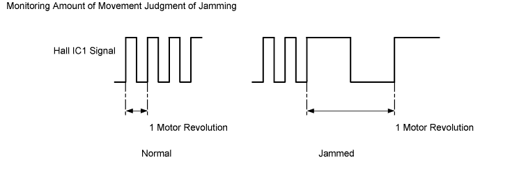
Jam Protection
-
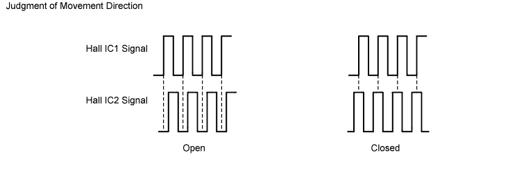
To control the jam protection function, the sliding roof control ECU monitors the amount of movement and judges jamming of the roof sunshade based on the pulse signals from Hall IC1, and the moving direction of the roof sunshade from the phase difference between the pulses from Hall IC1 and Hall IC2.
-
-
-
FAIL-SAFE
-
Roof Sunshade System
-
The fail-safe for roof sunshade system are as follows:
Function Outline Position Information Malfunction Judgment When this function determines that a position malfunction has occurred during operation, it makes the position information indefinite and renders the initialization incomplete. Continuous Operation Restriction If current is applied to the motor for 35 seconds or longer, this function stops the current. forced Learning Operation Unfix the position information and leave the initialization incomplete as a safeguard against an inability to close the shade completely. Hall IC Failure Judgment If one of the Hall ICs fails, the system uses the other Hall IC, which works, to perform only a motor lock judgment. If both Hall ICs fail, the system will perform a manual operation in which the overload reverse operation is prohibited. Open Circuit Process If the system is unable to receive communication signals, it will hold the last received data for 120 milliseconds. Then, it will resume the default setting. Manual Close Operation after Stopping due to Open Overload Detection If the system detects an overload (ordinary load or seized motor) while opening the sunshade, it will stop the shade and perform a manual close operation in which the shade open operation is prohibited. Reset Relearning Function If the CPU is reset during a shade open or shade close operation, the system will perform this function when the position information becomes usable.
-
-
-
DIAGNOSIS
-
If the roof sunshade motor malfunctions, a Diagnostic Trouble Code (DTC) is stored in the sliding roof ECU. The DTC can be read by connecting the intelligent tester II to DLC3.
-