REAR SUSPENSION SYSTEM DETAILS
-
CONSTRUCTION
-
Rear Suspension Support Assembly
-
High damping rubber is used to improve ride comfort.
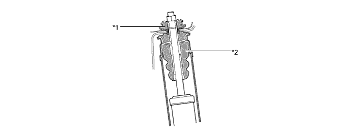
Text in Illustration *1 Rear Suspension Support Assembly *2 Rear Bumper Spring
-
-
Rear Coil Spring
-
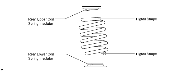
Both ends of the rear coil spring have been formed into a small-diameter, pigtail shape. The compact construction has been designed to accommodate the low floor package.
-
An insulator has been provided at both the upper and lower ends and the rubber thickness has been optimized to achieve a high level of vibration isolation performance and ride comfort.
-
-
Rear Shock Absorber Assembly
-
A low-pressure (N2) gas sealed rear shock absorber assembly with a multi-leaf type linear control valve is used to achieve both driving stability and riding comfort.
-
A rebound spring is used to improve roll angle and roll posture.
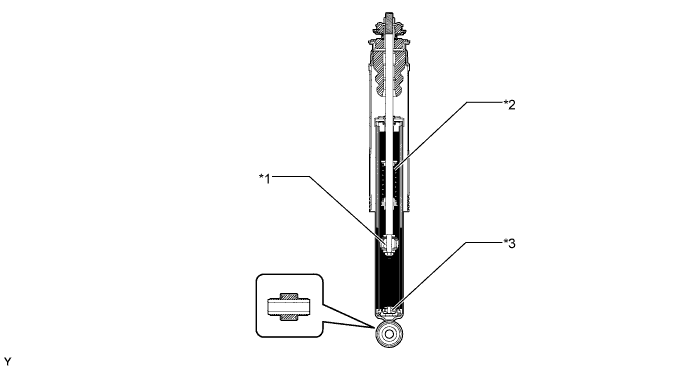
Text in Illustration *1 Piston Valve *2 Rebound Spring *3 Base Valve - - Tech Tips
To prevent hazardous conditions, make sure to empty the gas from the rear shock absorber assembly before discarding the low-pressure (N2) gas sealed in the rear shock absorber assembly. For details, refer to the AVENSIS Repair Manual.
-
-
Rear Trailing Arm Assembly
-
The rear trailing arm assembly uses high-strength sheet steel to achieve weight reduction and high rigidity.
-
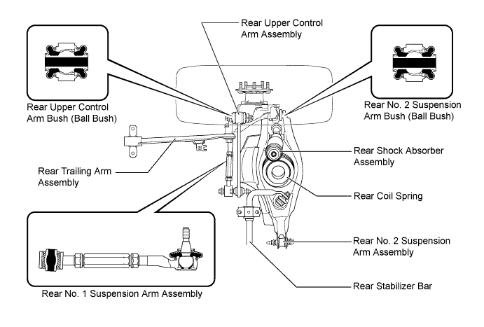
The bush with an outer cylinder has optimized characteristics to achieve excellent ride comfort.
-
-
Rear Upper Control Arm Assembly
-
The rear upper control arm assembly uses high-strength sheet steel to achieve weight reduction and high rigidity.
-
The rear suspension member sub-assembly side uses a bush with an outer cylinder, and the rear axle carrier sub-assembly side uses a ball bush.
-
-
Rear No. 1 Suspension Arm Assembly
-
The rear No. 1 suspension arm assembly uses a toe adjustment mechanism.
-
The rear suspension member sub-assembly side uses a bush with an outer cylinder, and the rear axle carrier sub-assembly side uses a ball joint.
-
-
Rear No. 2 Suspension Arm Assembly
-
The rear No. 2 suspension arm assembly uses high-strength sheet steel to achieve weight reduction and high rigidity.
-
The rear suspension member sub-assembly side uses a bush with an outer cylinder, and the rear axle carrier sub-assembly side uses a ball bush.
-
-
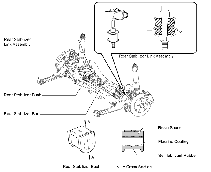
Rear Stabilizer Bar
-
A highly rigid, solid type rear stabilizer bar is used.
-
A ball joint is used between the rear stabilizer link assembly and the rear stabilizer bar. The space between the rear stabilizer link assembly and rear No. 2 suspension arm assembly is cushion-structured.
-
An assembly structure made of self-lubricant rubber and a resin spacer is provided for the rear stabilizer bush. The use of the resin spacer optimizes the rubber's characteristics to ensure high support rigidity.
-
To reduce friction, a fluorine coating is provided in the bore diameter of the rear stabilizer bush.
-
-