SFI SYSTEM DETAILS
-
FUNCTION OF MAIN COMPONENTS
-
The main components of the 1AZ-FE engine control system are as follows:
Component Function Quantity ECM 32-bit 1 Crankshaft Position Sensor (Rotor Teeth) Pick-up Coil Type (36-2) 1 No. 1 Crankshaft Position Sensor (Camshaft Position Sensor) (Rotor Teeth) Pick-up Coil Type (3) 1 Throttle Position Sensor Linear Type 1 Knock Sensor Built-in Piezoelectric Element Type (Flat Type) 1 Fuel Injector Assembly 4-hole Type 4 Tech Tips
-
The CPU of the ECM has been changed from 16-bit to 32-bit to increase the speed of signal processing.
-
The length of time to clear the Diagnostic Trouble Code (DTC) via the battery terminal has been changed from the previous 10 seconds to 1 minute.
-
-
-
SYSTEM CONTROL
-
The main components of the 1AZ-FE engine control system are as follows:
System Function Sequential Multiport Fuel Injection (SFI) -
An L-type SFI system directly detects the intake air mass with a hot-wire type air flow meter.
-
The fuel injection system is a sequential multiport fuel injection system.
Electric Throttle Control System-intelligent (ETCS-i) Optimally controls the throttle valve opening in accordance with the amount of accelerator pedal effort, the throttle valve opening control request from the ECM, and the condition of the engine and the vehicle. Electronic Spark Advance (ESA) Ignition timing is determined by the ECM based on signals from various sensors. The ECM corrects ignition timing in response to engine knocking. Fuel Pump Control -
Fuel pump operation is controlled by signals from the ECM.
-
The fuel pump is stopped, when the Supplemental Restraint System (SRS) airbag is deployed in a front or side collision.
Evaporative Emission Control The ECM controls the purge flow of evaporative emissions (HC) in the charcoal canister in accordance with engine conditions. Air Conditioning Cut-off Control*1 By turning the air conditioning compressor on or off in accordance with the engine condition, driveability is maintained. Cooling Fan Control Radiator cooling fan operation is controlled by signals from ECM based on the water temperature sensor signal (THW) and the condition of the air conditioner operation. Starter Control*2 Once the engine switch is pushed, this control continues to operate the starter until the engine is started. Diagnosis When the ECM detects a malfunction, the ECM diagnoses and memorizes the failed section. Fail-safe When the ECM detects a malfunction, the ECM stops or controls the engine according to the data already stored in memory. -
*1: Models with air conditioning
*2: Models with entry and start system
-
-
-
FUNCTION
-
Electronic Throttle Control System-intelligent (ETCS-i)
-
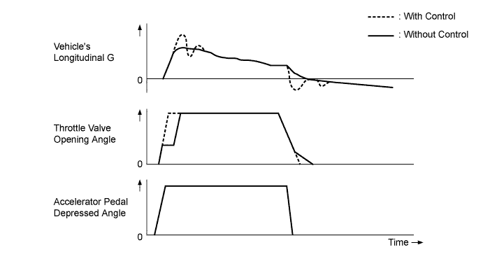
The ETCS-i is used, providing excellent throttle control in all the operating ranges. In the 1AZ-FE engine, the accelerator cable has been discontinued, and an accelerator pedal position sensor has been provided on the accelerator pedal.
-
In the conventional throttle body, the throttle valve opening is determined by the amount of the accelerator pedal effort. In contrast, the ETCS-i uses the ECM to calculate the optimal throttle valve opening that is appropriate for the respective driving condition and uses a throttle control motor to control the opening.
-
The ETCS-i controls the Idle Speed Control (ISC) system
In case of an abnormal condition, this system switches to the limp mode.
-
-
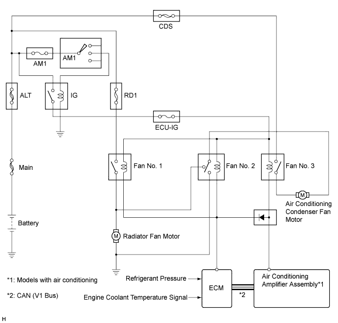
Cooling Fan Control
-
In contrast to the previous electric cooling fan system, the cooling fan main relay and the E.F.I. engine coolant temperature switch have been discontinued. Instead, by sharing the E.F.I. engine coolant temperature sensor to control the fan motor, a simpler system has been achieved.
-
This cooling fan control turns 3 fan relays on/off in accordance with the E.F.I. engine coolant temperature and the operating conditions of the air conditioning system. When it is on, the control is switched to operate the 2 fan motors at low (serial) or high (parallel).
-
-
Ignition System
-
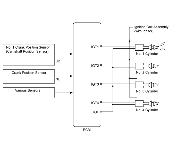
Direct Ignition System
-
A Direct Ignition System (DIS) is used. The DIS improves the ignition timing accuracy, reduces high-voltage loss, and enhances the overall reliability of the ignition system by eliminating the distributor.
-
The DIS in this engine is an independent ignition system which has 1 ignition coil (with igniter) for each cylinder.
-
The DIS provides 4 ignition coils, one for each cylinder. The spark plug caps, which provide contact to the spark plugs, are integrated with an ignition coil. Also, an igniter is enclosed to simplify the system.
-
-
Spark Plug
-
Platinum-tipped spark plugs are used.
Manufacturer Type Plug Gap DENSO made SK20R11 1.0 mm to 1.1 mm (0.039 in. to 0.043 in.) NGK made BKR6EYA11
-
-
-
Serpentine Belt Drive System
-
Accessory components are driven by a serpentine belt consisting of a single V-ribbed belt. It reduces the overall engine length, weight and number of engine parts.
-
An automatic tensioner eliminates the need for tension adjustment.
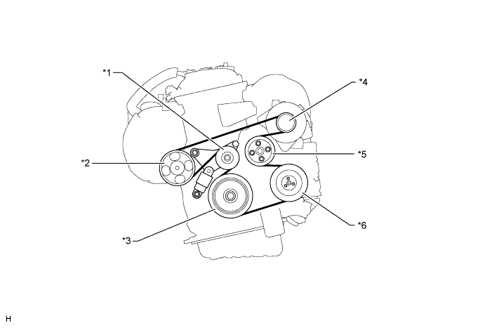
Text in Illustration *1 Tensioner Pulley *2 Idler Pulley *3 Crankshaft Pulley *4 Generator Pulley *5 Water Pump Pulley *6 Air Conditioning Compressor Pulley
-
-
Fuel Pump Control
-
An integrated fuel pump with charcoal canister is used to save space in the engine compartment and to reduce the number of component parts.
-
Driving range has been lengthened in consideration of fuel consumption improvement.
-
To secure good NV performance, rubber bushes are used to 4 fuel tank fixing portions.
-
As the height of the floor under the rear seat has been reduced by adopting a thinner fuel tank, the luggage height and the rear seat height have become the same.
-
-
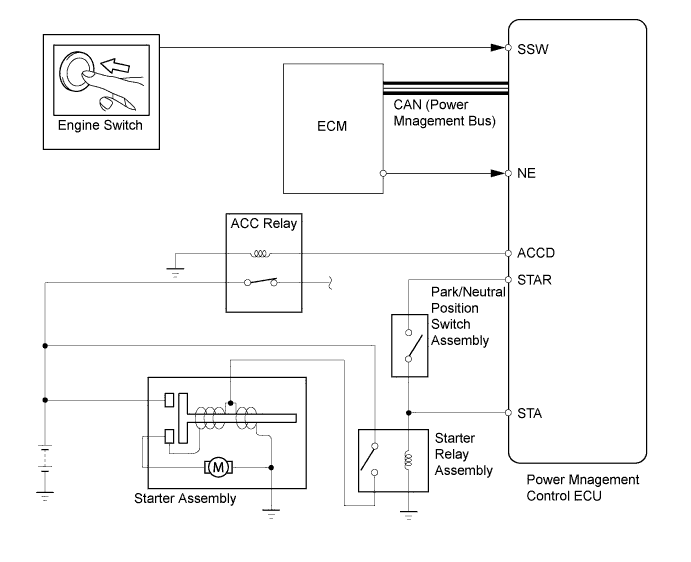
Starter Control (Models with entry and start system)
-
Once the engine switch is pressed, this function operates the starter until the engine starts, provided that the brake pedal is depressed and the shift lever is in P or N.
-
This prevents application of the starter for an inadequate length of time and it also prevents the engine from being cranked after it has started.
-
-
-
CONSTRUCTION
-
Throttle Position Sensor
-
Electrical throttle body is used.
-
Precise control and excellent reliability are achieved by adopting an electronic position sensor with a Hall IC. This also improves the response of the engine.
-
The throttle position sensor is mounted on the throttle body to detect the opening angle of the throttle valve. The throttle position sensor converts the magnetic flux density that changes when the magnetic yoke (located on the same axis as the throttle shaft) rotates around the Hall IC into electric signals to operate the throttle control motor.

-
-
Throttle Control Motor
-
A DC motor with excellent response and minimal power consumption is used for the throttle control motor. The ECM performs the duty ratio control of the direction and the amperage of the current that flows to the throttle control motor in order to regulate the opening of the throttle valve.
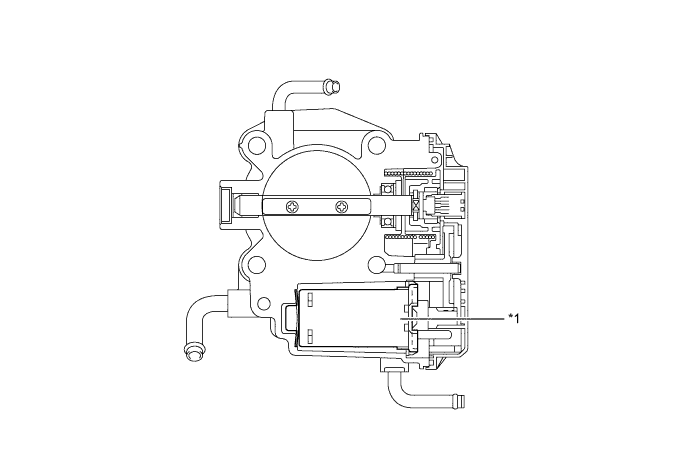
Text in Illustration *1 Throttle Motor - -
-
-
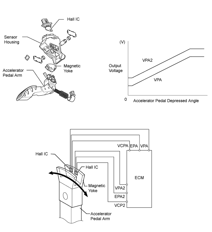
Accelerator Pedal Position Sensor
-
The non-contact type accelerator pedal position sensor uses a Hall IC.
-
The magnetic yoke mounted at the base of the accelerator pedal arm moves around the Hall IC in accordance with the amount of effort applied to the accelerator pedal. The Hall IC converts the changes in the magnetic flux that occur into electrical signals, and outputs them in the form of accelerator pedal effort to the ECM.
-
This accelerator pedal position sensor includes 2 Hall ICs and circuits for the main and sub signals. It converts the accelerator pedal depressed angles into electric signals with 2 differing characteristics and outputs them to the ECM.
-
-
-
OPERATION
-
The ECM drives the throttle control motor by determining the target throttle valve opening in accordance with the respective operating condition.
-
Non-linear Control
-
It controls the throttle to an optimal throttle valve opening that is appropriate for the driving condition such as the amount of the accelerator pedal effort and the engine speed in order to achieve excellent throttle control and comfort in all operating ranges.
-
-
Idle Speed Control
-
The ECM controls the throttle valve in order to constantly maintain an ideal idle speed.
-
-
Cooling Fan Control
Air Conditioning Condition Engine Coolant Temperature Compressor Refrigerant Pressure About 94°C (201°F) or lower About 95.5°C (204°F) or higher Off 1.2 MPa (12.5 kgf*cm2) or lower
Off High On 1.2 MPa (12.5 kgf*cm2) or lower
Low High 1.5 MPa (15.5 kgf*cm2) or higher
High High -
Starter Control
-
When the driver pushes the engine switch* once and the power management control ECU detects a start signal, the power management control ECU will output ACCD and STAR signals and begin cranking. Also, the driver can continue cranking for up to 30 seconds by pushing and holding the engine switch*.
*: Models with entry and start system
-
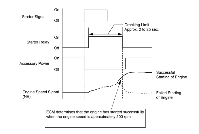
If the engine speed reaches approximately 500 rpm, the ECM will judge that the engine has started and will send a signal to the power management control ECU using CAN communication. The power management control ECU will then stop the operation of the starter.
-
If CAN communication is cut between the power management control ECU and the ECM, the power management control ECU will receive an engine speed signal (NE) directly from the ECM and will stop the operation of the starter.
-
This system will cut off the power current which activates the accessories while the engine is being cranked. This prevents the intermittent blinking of the accessory lights caused by the voltage instability that occurs during engine cranking.
-
This system has the following protections:
-
The starter will not operate if the engine is operating normally.
-
If the engine switch is pushed and held, cranking will stop once the engine speed reaches a pre-determined level. This prevents the starter from over-revving.
-
If the engine does not start even after approximately 6 seconds of starter operation, the power management control ECU will cancel the starter relay output. Furthermore, if the engine does not start after the engine switch has been pushed and held and cranking has continued for 30 seconds, cranking will be canceled in order to protect the starter.
-
It will not be possible to operate the starter for 2 seconds after engine starting has failed and cranking has been cancelled. This helps to protect the starter.
-
-
-