ENGINE UNIT DETAILS
-
FUNCTION OF MAIN COMPONENTS
-
Cylinder Head Cover
-
A lightweight magnesium alloy die-cast cylinder head cover is used.
-
Acrylic rubber, which excels in heat resistance and reliability, has been used for the cylinder head cover gasket.
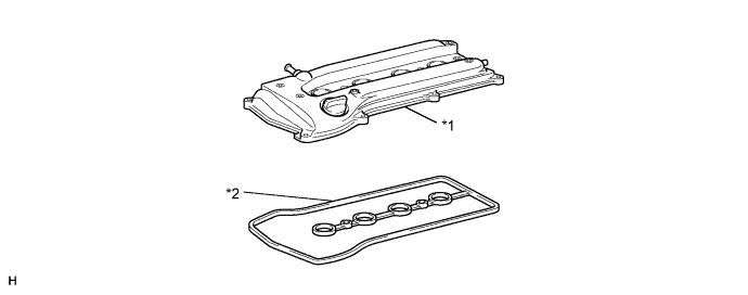
Text in Illustration *1 Cylinder Head Cover Sub-assembly *2 Cylinder Head Cover Gasket
-
-
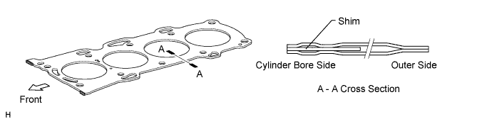
Cylinder Head Gasket
-
A steel-laminate type cylinder head gasket has been used.
-
A shim has been added around the cylinder bore to increase the sealing surface, thus improving the sealing performance and durability.
-
-
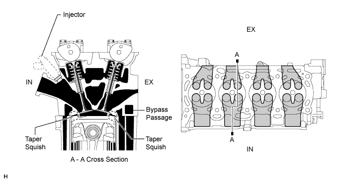
Cylinder Head
-
Through the usage of the taper squish combustion chamber, the engine knocking resistance and fuel efficiency have been improved.
-
An upright intake port is used to improve the intake efficiency.
-
Installing the injectors in the cylinder head enables the injectors to inject fuel as close as possible to the combustion chamber. This prevents the fuel from adhering to the intake port walls, which reduces HC exhaust emissions.
-
The routing of the water jacket in the cylinder head has been optimized to improve cooling performance. In addition, a water bypass passage has been provided below the exhaust ports to reduce the number of parts and to achieve weight reduction.
-
-
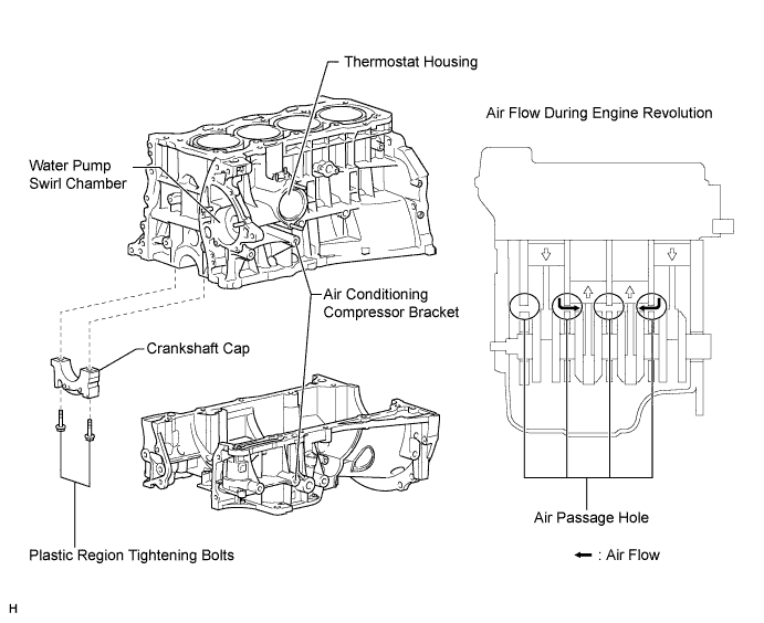
Cylinder Block
-
Lightweight aluminum alloy is used for the cylinder block.
-
By producing the thin cast-iron liners and cylinder block as a unit, a compact size has been achieved.
-
Passage holes are provided in the crankshaft bearing area of the cylinder block. As a result, the air at the bottom of the cylinder flows smoother, and pumping loss (back pressure at the bottom of the piston generated by the piston's reciprocal movement) is reduced to improve the engine's output.
-
The oil filter, air conditioning compressor bracket is integrated into the crankcase, and the thermostat housing and water pump swirl chamber are integrated into the cylinder block, thus reducing the number of parts.
-
-
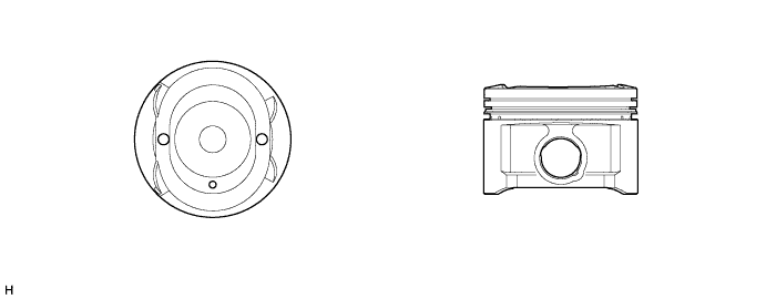
Piston
-
The piston is made of aluminum alloy and the skirt area is made compact and lightweight.
-
The piston head portion uses a taper squish shape to improve fuel combustion efficiency.
-
A full floating type piston pin is used.
-
By increasing the machining precision of the cylinder bore diameter, the outer diameter of the piston has been made into one type.
-
-
Connecting Rod
-
The connecting rods and caps are made of high strength material for weight reduction.
-
The plastic region tightening bolts are used.
-
The connecting rod bearings have been reduced in width to reduce friction.
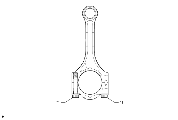
Text in Illustration *1 Plastic Region Tightening Bolts - -
-
-
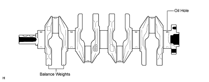
Crankshaft
-
The forged crankshaft has 5 journals and 8 balance weights.
-
The crankshaft bearings have been reduced in width to reduce friction.
-
The precision and surface roughness of the pins and journals have been improved to reduce friction.
-
-
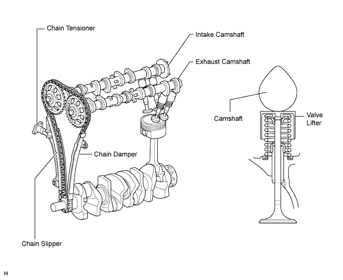
Valve Mechanism
-
Along with the increase in the amount of valve lift, the shim-less type of valve lifter is used. This valve lifter increases the cam contact surface.
-
The adjustment of the valve clearance is accomplished by selecting and replacing the appropriate valve lifters. A total of 35 valve lifters are available in 0.020 mm (0.008 in.) increments, from 5.060 mm (0.199 in.) to 5.740 mm (0.226 in.). For details, refer to the AVENSIS Repair Manual.
-
-
Camshaft
-
The intake camshaft is provided with a timing rotor to trigger the camshaft position sensor.
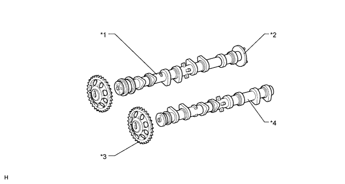
Text in Illustration *1 Intake Camshaft *2 Timing Rotor *3 Timing Sprocket *4 Exhaust Camshaft
-
-
Timing Chain
-
A roller chain with an 8 mm (0.315 in.)pitch has been used to make the engine more compact.
-
The timing chain is lubricated by an oil jet.
-
The chain tensioner uses a spring and oil pressure to maintain proper chain tension at all times.
-
The chain tensioner suppresses noise generated by the timing chain.
-
A ratchet type non-return mechanism is used.
-
To achieve excellent serviceability, the chain tensioner is constructed so that it can be removed and installed from the outside of the timing chain cover.
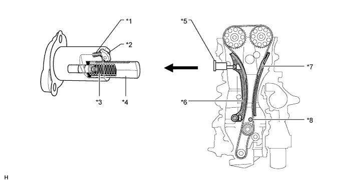
Text in Illustration *1 Cam Spring *2 Cam *3 Spring *4 Plunger *5 Chain Tensioner *6 Chain Slipper *7 Chain Damper *8 Oil Jet
-
-
Chain Cover
-
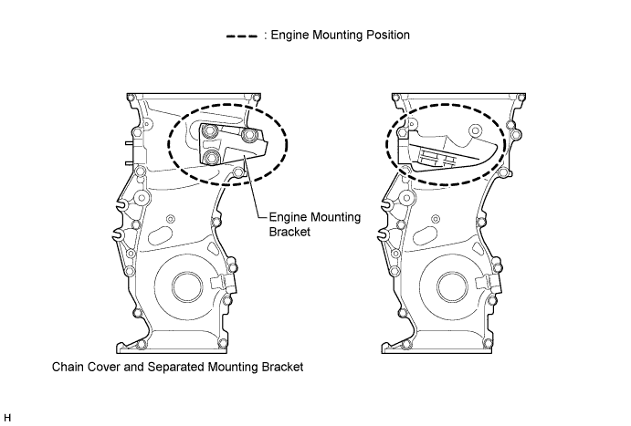
The newly designed engine mounting position results in lower engine roll vibration and better NV performance.
-
To realize this engine mounting position, the engine mounting bracket is separated from chain cover.
-
-
Engine Mount
-
This system has 4 point mount. It has the same type of engine mount system as the current model.
-
The right mount is the hydraulic type. The other mounts are the conventional rubber type.
-
The character has been optimized for the body. Through this adjustment, vehicle noise and vibration have been reduced.
-
The dynamic damper and the mass damper are set in the mount and mount bracket respectively in order to reduce engine noise and gear noise.
-
-