BODY STRUCTURE DETAILS
-
FUNCTION
-
Front Frame (Independent Type Front Suspension Model)
-
The front side rail and the center side rail have been welded together. This weld ensures a high level of rigidity because the welded area consists of a necked section that extends to the area immediately preceding the No. 3 cross member.
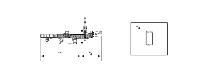
Text in Illustration *1 Front Side Rail *2 Center Side Rail *a A-A Cross Section - - 
Necked Section - - -
The front suspension members consist of two members that have been joined with pipes in order to realize a lightweight and highly rigid construction.
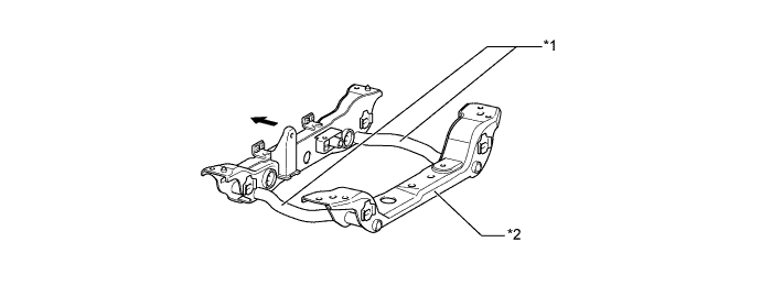
Text in Illustration *1 Pipe *2 Front Suspension Member 
Front - - -
A No. 3 cross member to which both the torsion bar anchor arms and the rear engine mounts can be mounted, has been adopted.

Text in Illustration *1 No. 3 Cross Member - - Front - -
-
-
Front Frame (Rigid Type Front Suspension Model)
-
To ensure rigidity, reinforcements have been riveted to the areas to which the front shock absorber brackets are to be mounted.
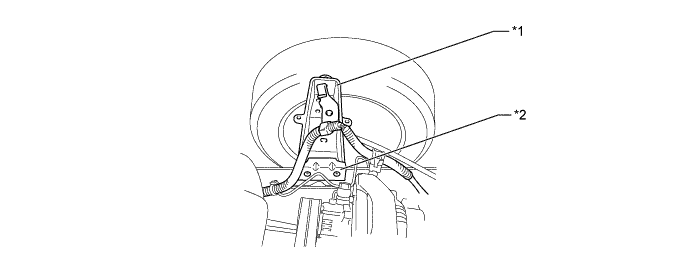
Text in Illustration *1 Front Shock Absorber Bracket *2 Reinforcement -
The No. 2 cross member has been riveted to the frame near the No. 1 spring bracket in order to ensure the rigidity of the area to which the suspension is to be mounted.
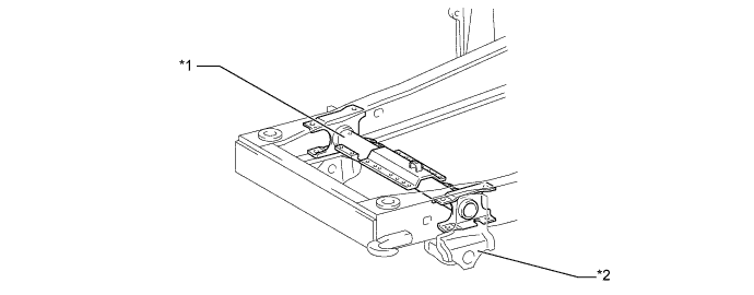
Text in Illustration *1 No. 2 Cross Member *2 No. 1 Spring Bracket
-
-
Rear Frame (Rear Side Rail)
-
The center side rail and the rear side rail have been riveted together.
-
The top of the rear side rail has been flattened in consideration of vehicle conversion applications.
-
The vertical face of the rear side rail has been lengthened at the center to realize enhanced rigidity.
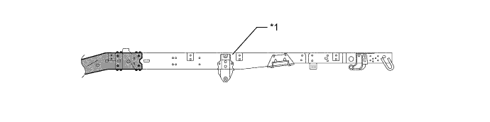
Text in Illustration *1 Flattened - - Riveted - - -
The new Dyna 100/150except for Europe comes with wheelbases in two length. The long wheelbase model forms the standard, and the front ends of the rear side rails have been shortened to create the short wheelbase model. The rear frame configurations are indicated in the table and the illustration below.
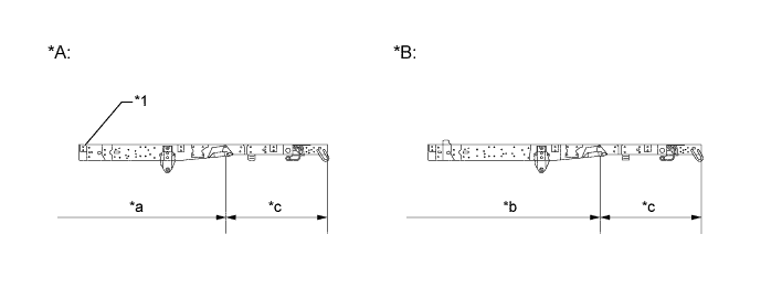
Text in Illustration *A Short Wheel Base *B Long Wheel Base *1 shortened at front end - - *a Wheel Base 2300 mm (90.6 in.) *b Wheel Base 2542 mm (100.2 in.) *c 1020 mm (40.2 in.) - -
-
-
Rear Frame (Cross Member)
-
On the independent type front suspension model, the center side rail and the rear side rail have been riveted together.
-
On the rigid type front suspension model, the front side rail and the rear side rail have been riveted together.
-
A No. 4 cross member has been allocated to the position of the No. 3 spring brackets to ensure the rigidity of the area to which the suspension is to be mounted. On the extra-long wheelbase model and the super long wheelbase model, the same cross member has been allocated to the area between the No. 3 and No. 4 cross members in order to support the center bearing of the propeller shaft.
-
To provide clearance to the rear axle, a No. 5 cross member made of a pipe that is bent upward has been adopted. To contribute to weight reduction, the pipe has a wall that is thinner at its middle than at its ends.
-
A No. 6 cross member has been allocated to the position of the No. 4 spring brackets. On the extra-long wheelbase model and the super-long wheelbase model, the same cross member has been allocated to the back of the rails to improve the rigidity of the back end of the rear side rails.
-
The spring brackets are riveted to the rear side rails.
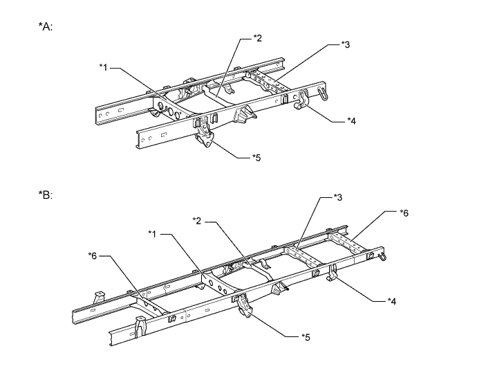
Text in Illustration *A Long Wheel Base *B Extra Long Wheel Base *1 No. 4 Cross Member *2 No. 5 Cross Member *3 No. 6 Cross Member *4 No. 4 Spring Bracket *5 No. 3 Spring Bracket *6 Cross Member
-
-
Rear Frame (Rear Shock Absorber Bracket)
-
The right rear shock absorber bracket has been positioned in front of the rear axle, and the left rear shock absorber bracket has been positioned in the back of the rear axle. The right bracket is riveted to the rear side rail and the left bracket is welded to the rear inner channel.
-
The rear inner channel, to which the left rear shock absorber bracket is mounted, is riveted to the inside of the rear side rail located between the No. 5 cross member and No. 6 cross member.
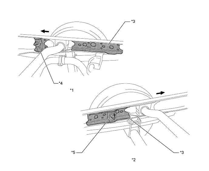
Text in Illustration *1 RH Rear Side Rail *2 LH Rear Side Rail *3 Inner Channel *4 RH Rear Shock Absorber Bracket *5 LH Rear Shock Absorber Bracket - - Front - -
-
-
Auxiliary Cross Member
-
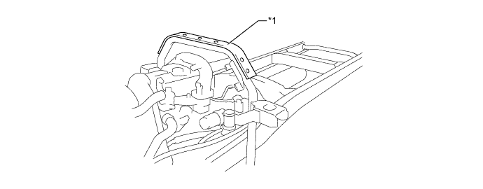
An auxiliary cross member, which consists of a pipe that joins the rear cab mounts has been adopted in order to disperse the force that is applied to the mounts. Furthermore, this cross member contributes to improving the torsional rigidity of the frame.
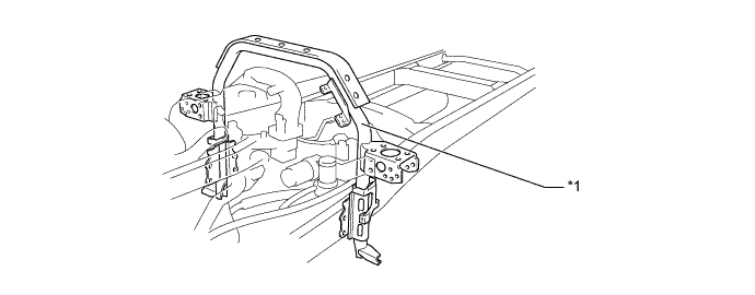
Text in Illustration *1 Auxiliary Cross Member - -
-
-
Door
-
Pipe type side impact protection beam is installed in the center space between the outer and inner front door panels.
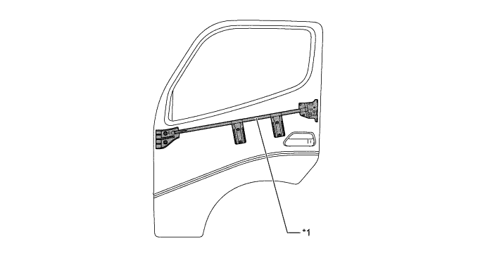
Text in Illustration *1 Side Impact Protection Beam - -
-
-
-
CONSTRUCTION
-
Anti-Corrosion Sheet Steel
-
Anti-corrosion sheet steel is used for many inner and outer panels of the body shell such as the front panel, side member outer panels, door inner panel and door outer panel in order to further improve rust-resistant performance.
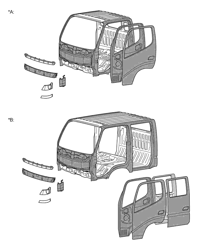
Text in Illustration *A Single Cab Model *B Double Cab Model Anti-Corrosion Sheet Steel - -
-
-
Wax and Sealer
-
Wax and sealer is applied to the hemmed portions of the doors, around hinges and at the joints between panels to improve rust-resistant performance.
-
-
Under Coat
-
To improve rust-resistant performance, PVC (Polyvinyl chloride) coating is applied to the under side of the cab which are subject to damage by stone chipping.
-
The inside of the rear fenders of the deck of the complete model has been coated with PVC (polyvinyl chloride).
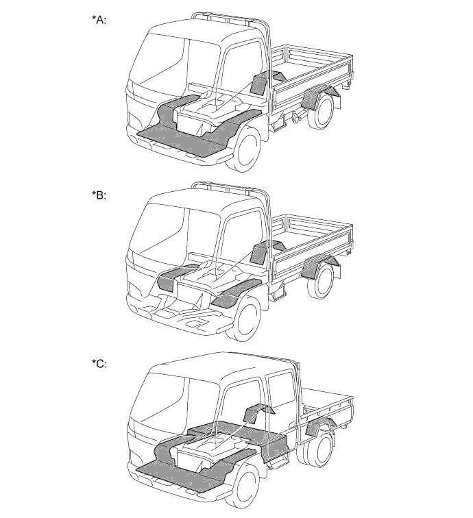
Text in Illustration *A Single Cab Models for Europe *B Models except for Europe *C Double Cab Models for Europe - - PVC Coating Area - -
-
-
Sound Absorbing and Vibration Damping Materials
-
Asphalt sheet is applied to most of the floor area to reduce engine and road noise during vehicle operation.
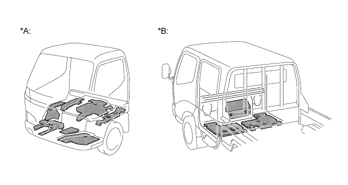
Text in Illustration *A Single Cab Model *B Double Cab Model Asphalt Sheet - - -
Foamed seal materials are applied onto the front panel and pillars to reduce wind and road noise.
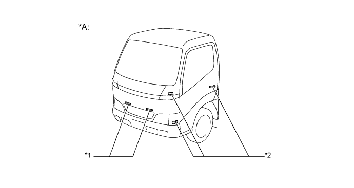
Text in Illustration *A Single Cab Model - - *1 Foamed Seal Material - -
-
-
Cab
-
Reinforcements have been provided in the front floor cross member in order to improve the rigidity of the frame and thus reduce the generation of droning noise.
-
The back panel has been made not to resonate with the engine noise or the drive train vibration by effectively allocating its vertical beads and members.
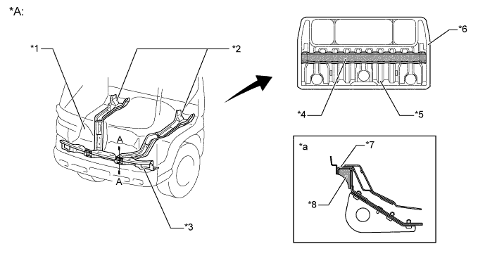
Text in Illustration *A Single Cab Model - - *1 Front Floor Panel *2 Floor Side Member *3 Front Floor Cross Member *4 Member *5 Vertical Bead *6 Back Panel *7 Front Floor Cross Member *8 Reinforcement *a A-A Cross Section - -
-
-
Cab Mount (for Europe)
-
A front cab mount in which a rubber cushion and a bracket have been combined has been adopted. This resulted in reducing noise and vibration and improving ride comfort.
-
Rear cab mounts that support the two different types of constructions of the single-cab and double-cab models have been adopted. This has resulted in reducing noise and vibration and improving ride comfort.
-
No. 3 cab mounts have been provided on the double-cab model. These cab mounts are the compression type.
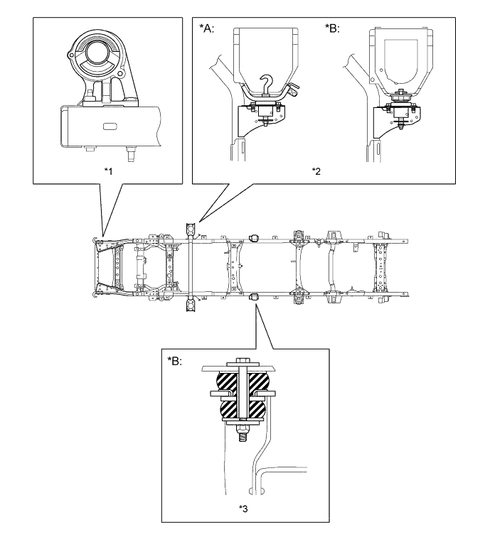
Text in Illustration *A Single Cab Model *B Double Cab Model *1 Front Cab Mount *2 Rear Cab Mount *3 No. 3 Cab Mount - -
-
-
Cab Mount (Except for Europe)
-
Compression type mounts have been adopted for the front and rear cab mounts of the rigid type front suspension model. These mounts provide revised spring characteristics that have been designed to reduce noise and vibration and to improve ride comfort.
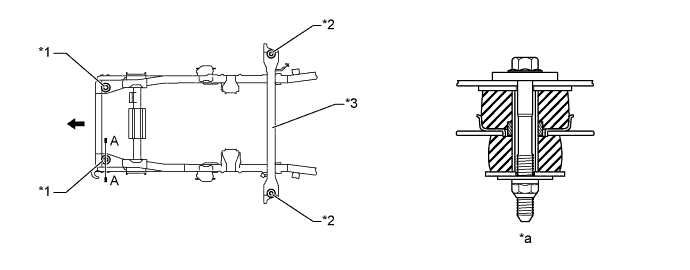
Text in Illustration (Rigid Type Front Suspension Model:) *1 Front Mounts *2 Rear Mounts *3 Auxiliary Cross Member - - *a A-A Cross Section - - Front - - -
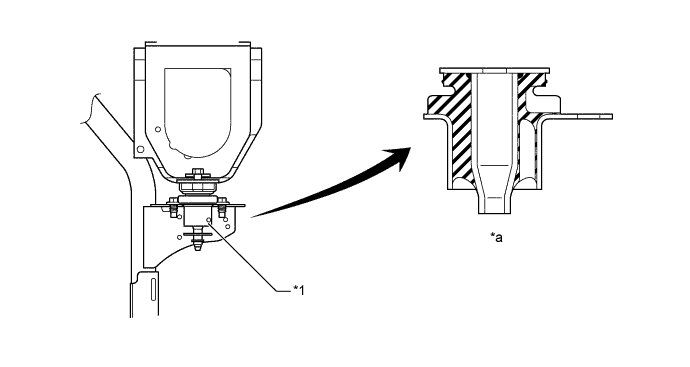
A front cab mount in which a rubber cushion and a bracket have been combined has been adopted on the independent type front suspension model. This resulted in reducing noise and vibration and improving ride comfort.
Text in Illustration (Independent Type Front Suspension Model:) *1 Rubber Cushion *2 Bracket *3 Frame - - *a A-A Cross Section - - Front - - -
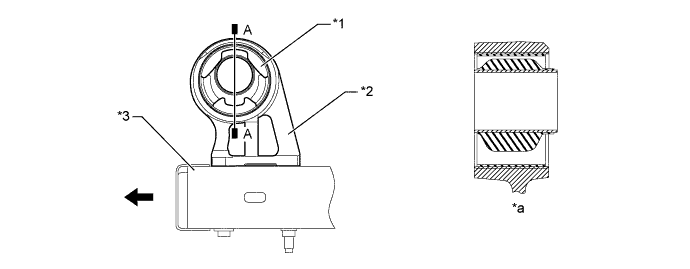
A shear type rear cab mount has been adopted on the independent type front suspension model. This resulted in reducing noise and vibration and improving ride comfort.
Text in Illustration (Independent Type Front Suspension Model:) *1 Rear Cab Mount - - *a Rear Cab Mount Cross Section - -
-
-
Steel Deck (Only for Complete Model)
-
The protrusion on the inside at the front of the deck has been eliminated to improve the ease of use.
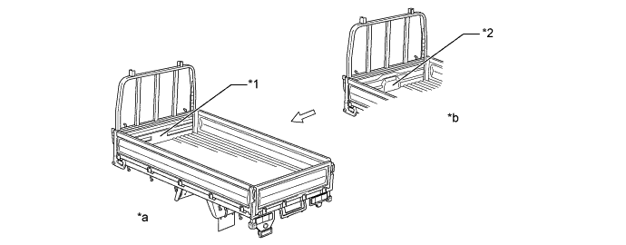
Text in Illustration *1 Flattened *2 Protrusion *a New *b Previous
-
-
Arch Cover (Only for Single Cab Model)
-
To prevent debris from entering the vicinity of the engine compartment or the exhaust pipe from behind the cab, an arch cover has been provided on the auxiliary cross member of the independent type front suspension model.
Text in Illustration *1 Arch Cover - -
-
-
Tilt Cab Mechanism (Only for European Single Cab Model)
-
A tilt-cab mechanism has been adopted on the single-cab model to improve serviceability.
-
For the tilt cab mechanism, a single torsion bar spring type has been adopted.
-
To ensure safety, a tilt stopper is used for the tilt stay.
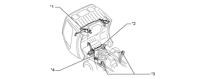
Text in Illustration *1 Cab Lock *2 Single Torsion Bar Spring *3 Rear Cab Mount *4 Tilt Stay -
To ensure safety, a tilt stopper is used for the tilt stay. This stopper prevents the lock of the stay that engages when the cab is in the full-tilt state from becoming disengaged.
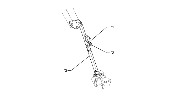
Text in Illustration *1 Tilt Stopper *2 Tilt Lock *3 Tilt Stay - -
-
-