AIR CONDITIONING SYSTEM DETAILS
-
CONSTRUCTION
-
Front Heater Blower Assembly
-
For the purpose of improving its heating performance, a recirculation air mixing door that can partially mix the recirculation air while operating in the fresh-air mode has been provided in the front heater blower assembly. This door is automatically opened and closed by the vacuum that is created when the heater blower fan sub-assembly operates, without requiring the driver to control it.
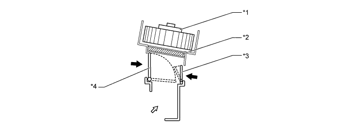
Text in Illustration *1 Heater Blower Fan Sub-assembly *2 Internal Air Filter (No. 2 Heater Air Filter) *3 Recirculation Air Mixing Door *4 Recirculation Air/Fresh-Air Switchover Damper 
Internal Air 
External Air
-
-
Heater Core (Heater Radiator Unit Sub-assembly)
-
A compact, lightweight, and highly efficient straight flow (full-path flow) aluminum heater core (heater radiator unit sub-assembly) has been adopted.
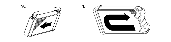
Text in Illustration *A Straight Flow *B U-turn Flow (Reference) Flow of Engine Coolant - -
-
-
Air Filter
-
An internal air filter (No. 2 heater air filter), which removes dust, is provided in the front heater blower assembly as standard equipment. It is positioned below the heater blower fan sub-assembly in the blower case in order to clean the fresh air that is introduced into the cabin as well as the air that is being recirculated in the cabin.
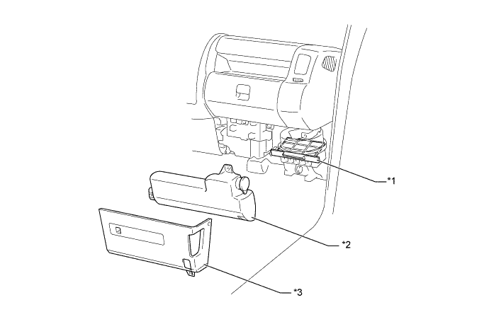
Text in Illustration *1 Internal Air Filter (No. 2 Heater Air Filter) *2 Windshield Washer Motor and Pump Assembly *3 Instrument Cluster Finish Panel - - -
External air filter (heater air filter) to remove the dust coming from outside has been established at the external air inlet inside the radiator grille.
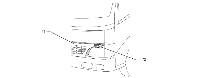
Text in Illustration *1 Radiator Grille (Remove it) *2 External Air Filter (Heater Air Filter)
-
-
-
OPERATION
-
Air Outlets and Airflow Volume
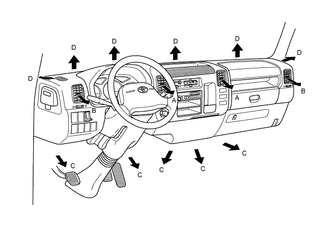
Indication Mode A B C D Center Side Foot Defroster 
FACE 
- - 
BI-LEVEL 
- 
FOOT - - 
FOOT/DEF - 
DEF - - Tech Tips
○: The airflow volume is represented by the size of the circle.
-