BRAKE CONTROL SYSTEM DETAILS
-
FUNCTION OF MAIN COMPONENTS
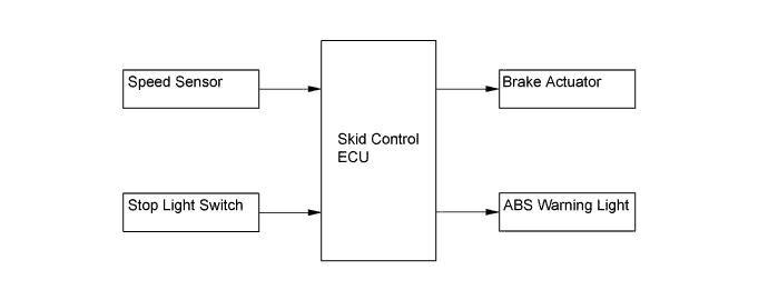
Components Function ABS Warning Light Light up to alert the driver when the skid control ECU detects the malfunction in the ABS. Skid Control ECU Based on the signals from each speed sensor, it calculates slip values and sends signals to the actuator and relay to control brake fluid pressure. Speed Sensors Detect the wheel speed of each of four wheels. Brake Actuator Changes the fluid path based on the signals from the skid control ECU during the operation of the ABS, in order to control the fluid pressure that is applied to the wheel cylinders. Control Relay Pump Motor Relay Supply power to the pump motor in the actuator. Solenoid Relay Supply power to the solenoid valves in the actuator. Stop Light Switch Detects the brake depressing signal. -
SYSTEM CONTROL
-
Anti-lock Brake System (ABS)
-
The ABS controls the brake fluid pressure acting on the wheel cylinders to help preventing the wheels locking and thus helps to maintain good directional stability and steerability on slippery surfaces and during panic braking.
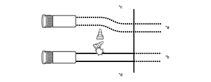
Text in Illustration *a Vehicle with ABS *b Vehicle without ABS *c Starting the Brake Application *d Conceptual Drawing
-
-
-
FUNCTION
-
Initial Check
-
After the ignition switch is turned ON, and the vehicle attains an approximate speed of 6 km/h (4 mph) or more only at first time, the skid control ECU performs an initial check. The functions of each solenoid valve and pump motor in the actuator are checked in order.
-
-
-
CONSTRUCTION
-
Brake Actuator
-
The brake actuator consists of six two-position solenoid valves, 1 motor, 2 pumps and 2 reservoirs. The six two-position solenoid valves consists of 3 pressure holding valves and 3 pressure reduction valves.
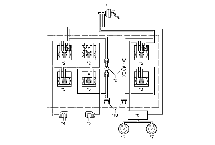
Text in Illustration *1 Master Cylinder *2 Pressure Holding Valve *3 Pressure Reduction Valve *4 Front Left Wheel Cylinder *5 Front Right Wheel Cylinder *6 Rear Left Wheel Cylinder *7 Rear Right Wheel Cylinder *8 LSP & BV *9 Pump *10 Reservoir
-
-
-
OPERATION
-
ABS
-
Based on the signals received from the 4 wheel speed sensors, the skid control ECU calculates each wheel speed, and checks wheel slipping condition. And according to the slipping condition, the ECU controls the pressure holding valve and pressure reduction valve in order to adjust the fluid pressure of each wheel cylinder in the following 3 modes: pressure reduction, pressure holding and pressure increase modes.
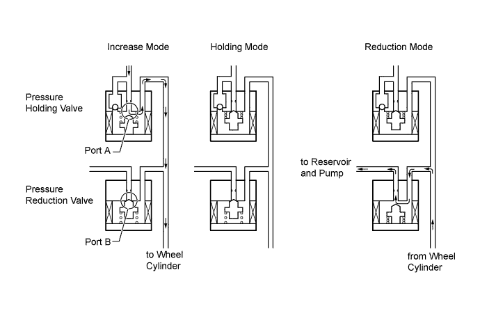
Not Activated Normal Braking - - Activated Pressure Increase Mode Pressure Holding Mode Pressure Reduction Mode Pressure Holding Valve (Port A) OFF (Open) ON (Close) ON (Close) Pressure Reduction Valve (Port B) OFF (Close) OFF (Close) ON (Open) Wheel Cylinder Pressure Increase Hold Reduction
-
-
-
FAIL-SAFE
-
In the event of a malfunction in an input signal to the skid control ECU, the skid control ECU cuts off its current to the actuator. As a result, the brake system operates in the same way as in a vehicle without ABS and normal braking function is assured.
-
-
DIAGNOSIS
-
If the skid control ECU detects a malfunction in this system, it illuminates the ABS warning light to alert the driver. At the same time, the DTCs (Diagnostic Trouble Codes) are stored in memory. The DTCs can be read by connecting the SST (09843-18040) between the Tc and CG terminals of DLC3 and observing the blinking ABS warning light, or by connecting a hand-held tester.
-
This system has a speed sensor signal check function.
-
For details on the DTCs that are stored in skid control ECU memory and DTCs that are output through the sensor signal check function, see the Repair Manual.
-