INTAKE SYSTEM DETAILS
-
CONSTRUCTION
-
Throttle Body
-
The throttle body equipped with a rotary solenoid type throttle control motor is used to realize high EGR performance and to reduce the vibration and noise when the engine is stopped. The rotary solenoid type throttle control motor makes the throttle valve respond quickly.
-
A non-contact type throttle position sensor is used in the throttle body.
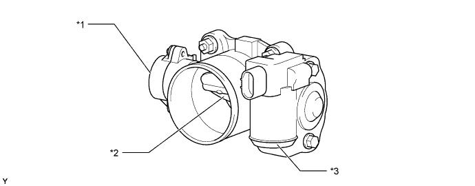
Text in Illustration *1 Throttle Position Sensor *2 Throttle Valve *3 Throttle Control Motor - -
-
-
Intake Manifold
-
An intake manifold provided with an air intake chamber is used in order to reduce the swirl variances between the cylinders.
-
A vacuum-actuated swirl control valve is provided in one of the two intake ports provided for each cylinder. A swirl control valve consists of a stainless steel shaft and an actuator, which are integrated in the valve.
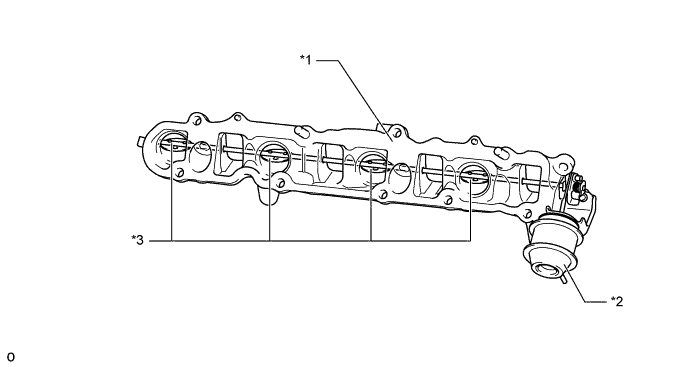
Text in Illustration (for Europe:) *1 Air Intake Chamber *2 Actuator *3 Swirl Control Valve - - 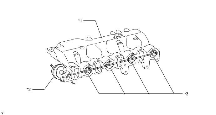
Text in Illustration (for Singapore:) *1 Air Intake Chamber *2 Actuator *3 Swirl Control Valve - -
-
-
Intercooler
-
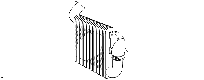
An air-cooled intercooler is used in order to lower the intake air temperature, improve engine performance, and realize clean exhaust gas emissions.
-
-
Turbocharger (for Europe)
-
A water-cooled variable nozzle vane type turbocharger manufactured by IHI Turbo is used.
-
By using the lightweight RHV4L turbocharger with a small turbine capacity and low-inertia momentum, the low speed engine torque and output power have been improved through ample supercharging at low engine speeds. This has improved the vehicle's usability as a commercial vehicle.
-
A high-response DC motor is used to drive the variable nozzle vane unit. A nozzle vane position sensor has also been fitted.
-
A cartridge-type variable nozzle vane unit which is supported by both axles is used to improve the performance of the turbocharger and to reduce its weight and size.
-
Semi-floating bearings are used on the turbine shaft to reduce the generation of oil whirl vibration.
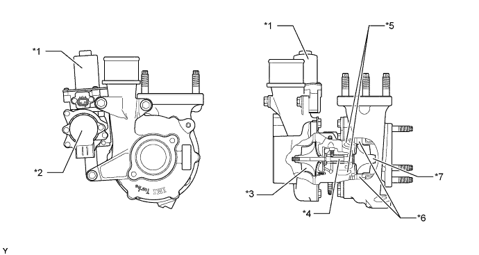
Text in Illustration *1 DC Motor *2 Nozzle Vane Position Sensor *3 Compressor Wheel *4 Turbine Shaft *5 Water Jacket *6 Variable Nozzle Vane *7 Turbine Wheel - - -
By combining the variable nozzle vane unit with a small-diameter turbine wheel, the turbine housing capacity and inertia momentum have been reduced.
-
The balance between back pressure and supercharging pressure is controlled optimally, in accordance with the engine speed and the vehicle load, through the nozzle vanes attached to the outer periphery of the turbine wheel and by adjusting the flow speed and pressure of the exhaust gas input into the turbine. In addition, the engine ECU outputs a signal to the turbo motor driver, which actuates the DC motor, to control the nozzle vane position.
-
The variable nozzle vane type turbocharger consists primarily of a turbine with a built-in variable nozzle vane unit, a compressor, a DC motor and a nozzle vane position sensor.
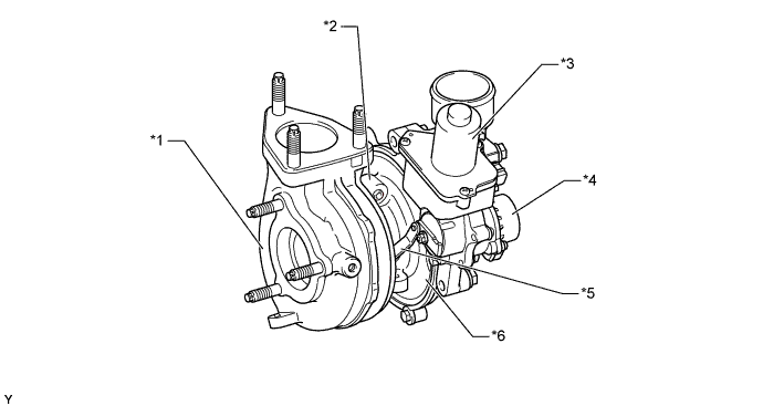
Text in Illustration *1 Turbine Housing (Built-in Turbine Wheel and Variable Nozzle Vane Unit) *2 Bearing Housing *3 DC Motor for Driving Nozzle vanes *4 Nozzle Vane Position Sensor *5 Link Plate for Driving Nozzle vanes *6 Compressor Housing -
The variable nozzle vane unit is a cartridge-type unit which is built into the turbine housing, and consists of a shroud, nozzle ring, drive ring, drive ring support and nozzle link plate, etc.
-
Each movable nozzle vane of the variable nozzle vane unit is supported by two axles; one on the shroud side and one on the nozzle ring side. The movement of the drive lever driven by the DC motor is transmitted to the drive ring as rotation, and the nozzle link plates and nozzle vanes that are combined with the drive ring are movable.
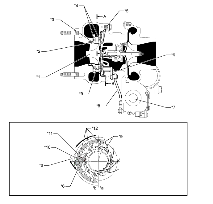
Text in Illustration *1 Turbine Wheel *2 Cartridge-type Variable Nozzle Vane Unit *3 Shroud *4 Both Axles for Nozzle Vane Unit *5 Nozzle Ring *6 Drive Lever *7 DC Motor *8 Link Plate *9 Nozzle Vane *10 Drive Plate *11 Drive Ring *12 Nozzle Link Plate *a A-A *b B-B Tech Tips
-
To control the nozzle vane position, the turbo motor driver renders the contact position of the drive lever and the full-close stopper (nozzle vane fully closed) as the zero point for the nozzle vane position sensor.
-
If the turbocharger has been reinstalled or replaced, turn the ignition switch from ON to OFF once, and make sure that the drive lever comes in contact with the full-close stopper.
-
The full-close stopper position, which is adjusted at the factory at the time of shipment, is not serviceable in the field. For this reason, if the drive lever does not come in contact with the full-close stopper during an inspection, the turbocharger assembly must be replaced. Never attempt to loosen or tighten the lock nut of the full-close stopper because it will adversely affect the performance of the engine.
-
For details, refer to the Repair Manual.
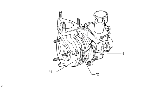
Text in Illustration *1 Full-close Stopper *2 Lock Nut *3 Drive Lever - -
-
-
-
Turbocharger (for Singapore)
-
A variable nozzle vane type turbocharger is used. A water jacket is provided in the bearing housing to improve the cooling performance of the turbocharger.
-
A DC motor for driving the variable nozzle vane is used. Also, a nozzle vane position sensor is used to detect the position of the nozzle vane.
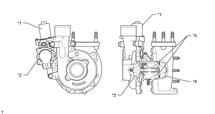
Text in Illustration *1 DC Motor *2 Nozzle Vane Position Sensor *3 Compressor Wheel *4 Turbine Wheel *5 Water Jacket - - -
This turbocharger has realized great improvements in low-speed torque, maximum output, fuel consumption, and emission reduction. These improvements have been accomplished through variable control of the nozzle vane position, and an optimal velocity of the exhaust gas inflow to the turbine wheel at all times in response to the engine condition.
-
The engine ECU outputs a signal to the turbo motor driver, which actuates the DC motor, to control the nozzle vane position.
-
The variable nozzle vane type turbocharger consists primarily of a compressor wheel, turbine wheel, nozzle vane, unison ring, drive arm, driven arm, DC motor, linkage and nozzle vane position sensor.
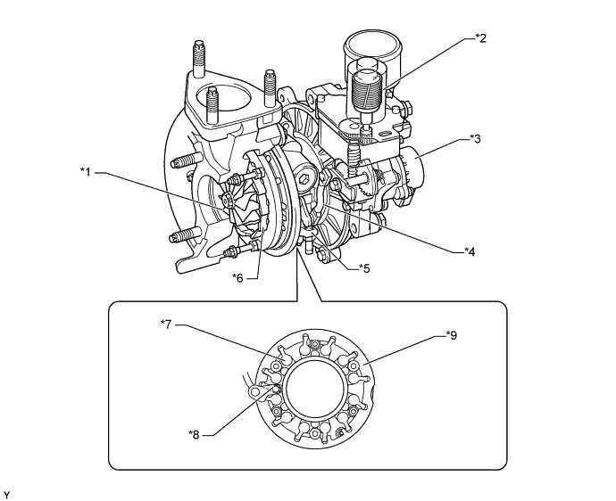
Text in Illustration *1 Turbine Wheel *2 DC Motor *3 Nozzle Vane Position Sensor *4 Linkage *5 Full-close Stopper *6 Nozzle Vane *7 Driven Arm *8 Drive Arm *9 Unison Ring - - Tech Tips
-
To control the nozzle vane position, the turbo motor driver renders the contact position of the linkage with the full-close stopper (thus fully closing the nozzle vane) as the zero point for the nozzle vane position sensor.
-
If the turbocharger has been reinstalled or replaced, turn the ignition switch from ON to OFF once, and make sure that the linkage comes in contact with the full-close stopper.
-
The full-close stopper position, which is adjusted at the factory at the time of shipment, is not serviceable in the field. For this reason, if the linkage does not come in contact with the full-close stopper during an inspection, the turbocharger assembly must be replaced. Never attempt to loosen or tighten the locknut of the full-close stopper because it will adversely affect the performance of the engine.
-
For details, refer to the Repair Manual.
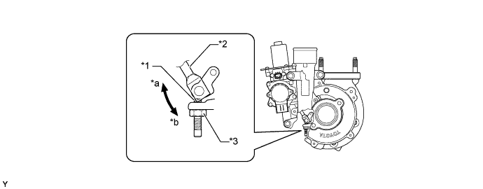
Text in Illustration *1 Full-close Stopper *2 Linkage *3 Lock Nut - - *a Open *b Close
-
-
-
-
OPERATION
-
Turbocharger
-
The exhaust gas from the exhaust manifold goes through the nozzle vane inside the turbo charger housing, and flows to the exhaust pipe through the turbine wheel. The speed of the turbine wheel (supercharging pressure) differs depending on the flow velocity of the exhaust gas going through the turbine wheel and the flow velocity of the exhaust gas is controlled by the opening angle of the nozzle vane. In such a time like idling, when the exhaust gas is less, the nozzle vane is almost fully closed, but as there is a slight clearance between the nozzle vanes, the exhaust gas flows through this clearance to the exhaust pipe. Therefore, there is no bypass as the conventional type turbocharger.

Text in Illustration *1 Compressor Wheel *2 Turbine Wheel *3 Nozzle Vane - - 
Exhaust Gas 
Intake Air -
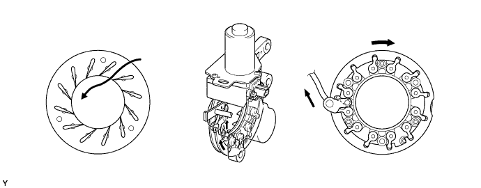
When the engine is running in a low speed range, the DC motor presses down the linkage by a signal from the turbo motor driver. The tip of the linkage rotates the unison ring counterclockwise through a drive arm. The unison ring contains a driven arm, which is placed through the cutout portion of the unison ring. This driven arm also moves in the direction of the rotation of the unison ring. The fulcrum of the driven arm is an axis that is integrated with the nozzle vane behind the plate. When the driven arm moves counterclockwise, the nozzle vane moves toward the closing direction. This results in increasing the velocity of the exhaust gas flowing to the turbine, as well as the speed of the turbine. As a result, torque is improved when the engine is running at low speeds.
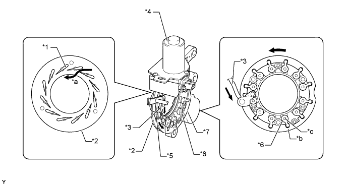
Text in Illustration *1 Nozzle Vane *2 Plate *3 Linkage *4 DC Motor *5 Drive Arm *6 Driven Arm *7 Unison Ring - - *a Gas Flow *b Cutout Portion *c Fulcrum - - -
When the engine is running in a medium-to-high speed range, the DC motor pulls up the linkage by a signal from the turbo motor driver. With this, the driven arm moves clockwise and this opens the nozzle vane and holds the specified supercharging pressure. Thus, the back pressure is lowered and the output and fuel consumption are improved.
-
-