EMISSION CONTROL SYSTEM DETAILS
-
SYSTEM CONTROL
-
EGR Control System (for Europe)
-
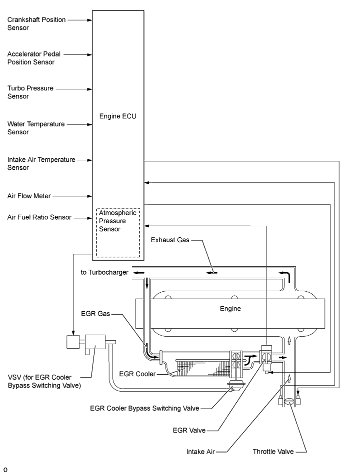
This system is designed to reduce and control NOx formation due to a slight reduction of peak temperature in the engine combustion chamber, which is accomplished by introducing a small amount of inert gas into intake manifold.
-
By sensing the engine driving conditions and actual amount of EGR valve opening, the engine ECU operates the DC motor type EGR valve and throttle control motor, and regulates the amount of recirculating exhaust gas.
-
-
EGR Control System (for Singapore)
-
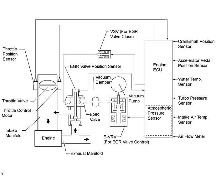
This system is designed to reduce and control NOx formation due to a slight reduction of peak temperature in the engine combustion chamber, which is accomplished by introducing a small amount of inert gas into intake manifold.
-
By sensing the engine driving conditions and actual amount of EGR valve opening, the engine ECU electrically operates the E-VRV (for EGR valve control) and VSV (for EGR valve close), which controls the magnitude of vacuum introduced into diaphragm of EGR valve and throttle valve opening angle by throttle control motor, and the amount of recirculating exhaust gas is regulated. EGR valve opening amount is controlled by modulated negative pressure.
-
The VSV (for EGR valve close) is activated when the EGR control is stopped, in order to introduce the atmospheric pressure to the EGR valve diaphragm and improve EGR valve closure response to maintain drivability.
-
The EGR function is stopped under the conditions given below to ensure drivability and to reduce diesel smoke.
-
While engine is cold.
-
The vehicle is under high load condition.
-
During deceleration (the EGR operation at idle).
-
-
-
Catalyst Support Control (for Europe)
-
If the DPF catalyst temperature is high under normal driving conditions, PM captured by the DPF catalyst is oxidized by the temperature of the DPF catalyst and is emitted as CO2 and H2O.
-
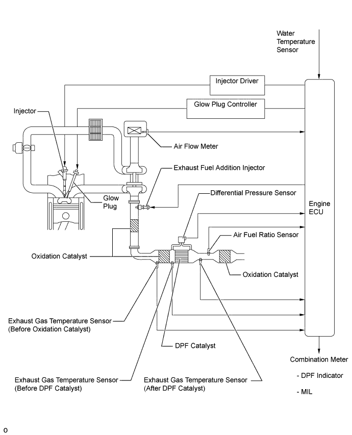
If the DPF catalyst temperature becomes low, catalyst performance decreases, resulting in an increase of the amount of PM stuck in the filter substrate. The engine ECU detects that the filter substrate is clogged by calculating the accumulated volume of the PM discharged by the engine. To reduce PM, the engine ECU controls the injection timing and the injection frequency of the injectors, and activates the exhaust fuel addition injector. At the same time, engine ECU controls the engine speed and glow plug assembly temperature via the glow plug controller.
-
As a result, filter substrate temperature becomes high and PM reacts with active oxygen and changes into CO2 for purification.
-
When PM has accumulated in the DPF catalyst while driving normally, the engine ECU automatically performs catalyst support control.
-
However, sufficient purification of the PM by the catalyst support control may not be possible when driving repeatedly over short distances. As a result, the PM accumulation limit may be surpassed. If catalyst support control is conducted in this situation, the DPF catalyst could be destroyed. To prevent this, the engine ECU calculates the level of PM accumulation. If a predetermined level has been surpassed, the DPF indicator in the combination meter is illuminated, thus prompting the driver to either drive at a constant speed or take the vehicle to a dealer.
-
Moreover, if the driver keeps driving without either bringing the vehicle to a dealer or driving at a constant speed, the MIL will be illuminated when a predetermined driving distance is reached. At the same time, the engine ECU changes the engine control to the fail-safe mode, thus controlling the amount of fuel injection to a minimum.
-
-
-
CONSTRUCTION
-
EGR Valve (for Europe)
-
The butterfly type EGR valve has been provided to reduce ventilation resistance and increase the valve ventilation amount. This allows the EGR volume to increase when the valve ventilation amount is very small to improve the EGR flow volume controllability.
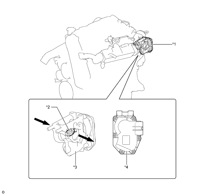
Text in Illustration *1 EGR Valve *2 Butterfly type Valve *3 DC Motor *4 EGR Valve Position Sensor 
EGR Gas - -
-
-
EGR Valve (for Singapore)
-
An EGR valve is provided in the midstream of the intake air passage. By cooling the EGR valve in this manner, a greater volume of exhaust gas can be processed.
-
A vacuum port for a VSV (for EGR valve close) to cut off EGR is used to improve valve closure response.
-
An EGR valve position sensor has been provided in the EGR valve in order to directly measure the actual amount of the valve opening. This measurement is then input into the engine ECU in order to improve the precision of EGR control.
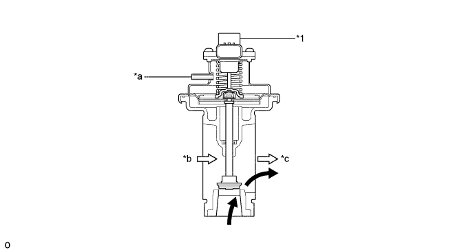
Text in Illustration *1 EGR Valve Position Sensor - - *a Vacuum Port *b from Air Cleaner *c to Intake Manifold - - EGR Gas 
Intake Air
-
-
EGR Cooler (for Europe)
-
A bypass integrated EGR cooler has been provided. In order to reduce pressure loss, a straight structure is used on the EGR cooler. In addition, an EGR cooler bypass switching valve is provided on the EGR cooler outlet. This allows the engine ECU to switch the EGR cooler passage between the bypass side and cooler side, making the EGR gas temperature variable.
-
A simple divided bypass type EGR cooler cooling path shape is used to reduce pressure loss. Furthermore, the core size has been increased to enhance the cooling efficiency, and the bypass path has been isolated to ensure the bypass efficiency.
-
Since the bypass valve has been provided on the EGR cooler outlet, the EGR gas flow path can be switched to the cooling side or the bypass side in accordance with the engine running conditions.
-
The EGR cooler bypass switching valve changes the cooling route to the cooler path or the bypass path via the VSV. Since the valve consists of 2 independent valves that are positioned 90° to each other, one valve remains closed while the other is open, and one valve opens while the other is closed.
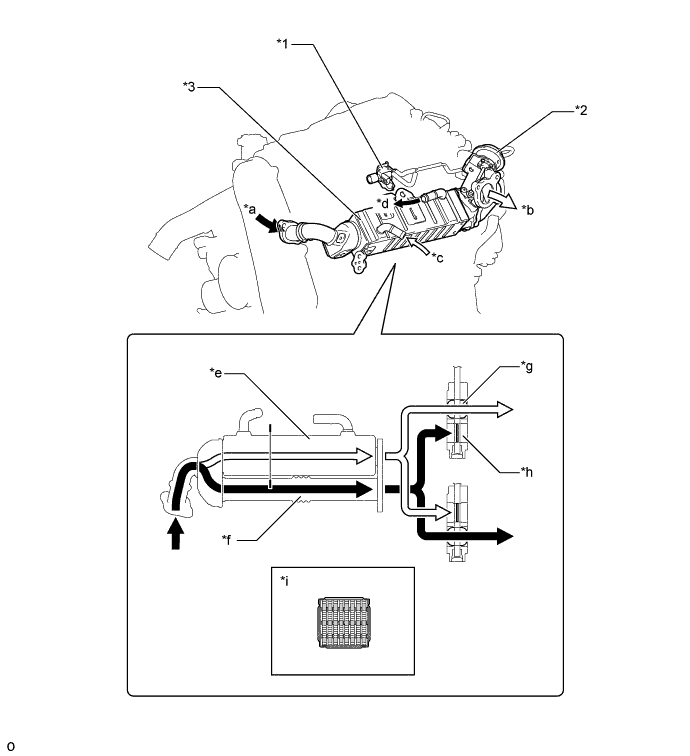
Text in Illustration *1 VSV (for EGR Cooler Bypass Switching Valve) *2 EGR Cooler Bypass Switching Valve *3 EGR Cooler - - *a EGR Gas Inlet *b EGR Gas Outlet *c Coolant Inlet *d Coolant Outlet *e Cooler Path *f Bypass Path *g EGR Gas Outlet Port (Cooler Side) *h EGR Gas Outlet Port (Bypass Side) *i A-A Cross Section - -
-
-
EGR Cooler (for Singapore)
-
A water-cooled type EGR cooler is used. That lowers the exhaust gas temperature to recirculate the great amount of exhaust gas, realizing the reduction of NOx.
-
The EGR cooler is comprised of the six-layered heat exchanger tube, which contains the inner fins inside.
-
The inner fins have a wavy shape to enhance cooling efficiency and prevent them from becoming clogged with carbon deposits. The water flows around the heat exchanger tubes to cool down the exhaust gas.
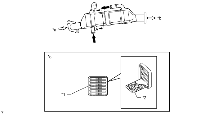
Text in Illustration *1 Heat Exchanger Tube *2 Inner Fin (Wavy Shaped) *a from Cylinder Head *b to EGR Valve *c A-A Cross Section - - Water Exhaust Gas
-
-
Exhaust Fuel Addition Injector (for Europe)
-
The exhaust fuel addition injector is located behind the turbocharger. This injector supplies additional fuel to DPF, and maintains the proper catalyst temperature for PM recovery.
-
The exhaust fuel addition injector consists of a body valve, needle valve and solenoid.
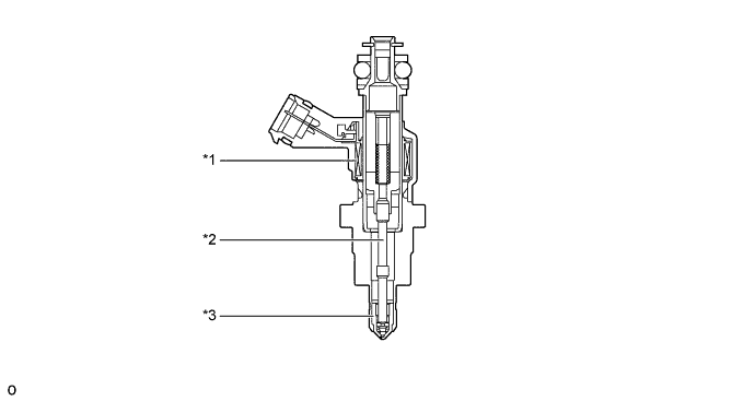
Text in Illustration *1 Solenoid *2 Needle Valve *3 Body Valve - -
-
-
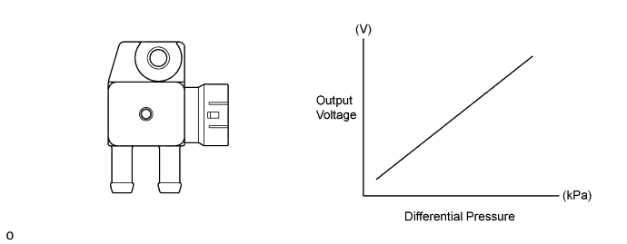
Differential Pressure Sensor (for Europe)
-
The differential pressure sensor measures the pressure difference between front and back of the DPF catalyst with PM in order to detect the occurrence of clogging.
-
The differential pressure sensor has connections ports for the high pressure side and low pressure side. In order to detect the difference in exhaust pressures between the DPF inlet and outlet, the high pressure port is connected to the area in front of the DPF catalyst and the low pressure port is joined to the area behind the catalyst.
-
-
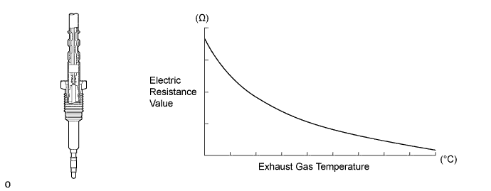
Exhaust Gas Temperature Sensor (for Europe)
-
An exhaust gas temperature sensor, which is a thermistor type, is installed before the oxidation catalyst, before the DPF catalyst and after the DPF catalyst, in order to detect the temperature of the exhaust gas.
-
-
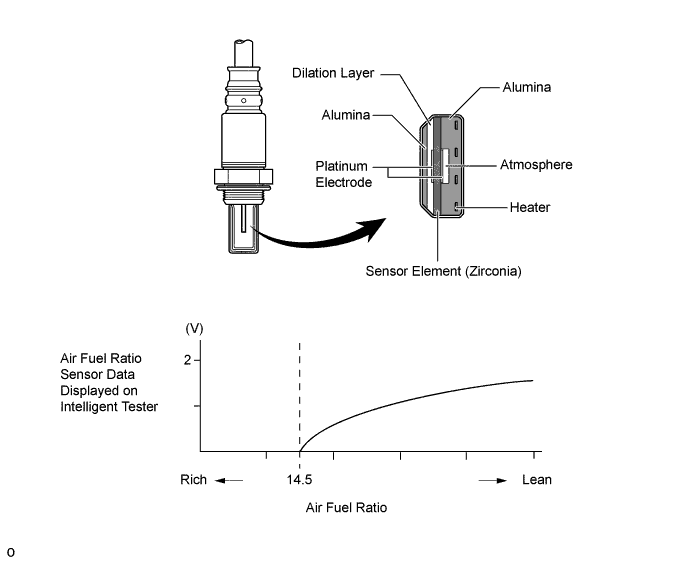
Air fuel Ratio Sensor (for Europe)
-
The planar type air fuel ratio sensor is used.
-
The planar type air fuel ratio sensor uses alumina, which excels in heat conductivity and insulation, to integrate the sensor element with the heater, thus improving the warm-up performance of the sensor.
-
This sensor is based on a sensor that is developed for gasoline engines. Its cover was changed for diesel engine application in order to eliminate the influences of the sensor temperature and the PM. This sensor, which is mounted after the DPF catalyst, detects the air fuel ratio after the gases are reduced.
-
The air fuel ratio sensor data is approximately proportional to the existing air fuel ratio. The air fuel ratio sensor converts the oxygen density to the current and sends it to the engine ECU.
-
-