EMISSION CONTROL SYSTEM DETAILS
-
SYSTEM CONTROL
-
EGR Control System
-
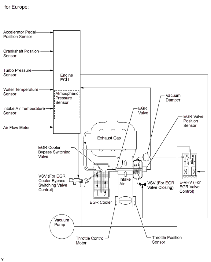
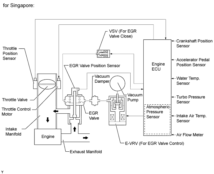
This system is designed to reduce and control NOx formation due to a slight reduction of peak temperature in the engine combustion chamber, which is accomplished by introducing a small amount of inert gas into intake manifold.
-
By sensing the engine driving conditions and actual amount of EGR valve opening, the engine ECU electrically operates the E-VRV (for EGR valve control) and VSV (for EGR valve close), which controls the magnitude of vacuum introduced into diaphragm of EGR valve and throttle valve opening angle by throttle control motor, and the amount of recirculating exhaust gas is regulated. EGR valve opening amount is controlled by modulated negative pressure.
-
The VSV (for EGR valve close) is activated when the EGR control is stopped, in order to introduce the atmospheric pressure to the EGR valve diaphragm and improve EGR valve closure response to maintain drivability.
-
The EGR function is stopped under the conditions given below to ensure drivability and to reduce diesel smoke.
-
While engine is cold.
-
The vehicle is under high load condition.
-
During deceleration (the EGR operation at idle).
-
-
For the European models, the engine ECU switches the bypass passage of the EGR cooler via the VSV (for EGR cooler bypass switching valve control) in order to optimize the temperature of the EGR gas and clean exhaust gases.
-
-
-
CONSTRUCTION
-
EGR Valve (for Europe)
-
An EGR valve is provided in the intake air passage to make EGR valve cooling by intake air possible, and, in combination with the use of a large capacity EGR cooler, has ensured reliability and an increased volume of EGR, reducing the level of NOx.
-
An outward-opening type EGR valve that is able to cope with the high back pressure of the exhaust system is used.
-
A partition is provided in the intake passage, taking the mixing characteristics of the EGR gas and intake air into consideration, and this has improved the efficiency of the distribution of the EGR gas to each cylinder.
-
An EGR valve lift sensor is provided. The movement of the valve is stabilized by accurate monitoring of the actual amount of EGR valve lift by the ECM, and thus precise EGR control is realized.
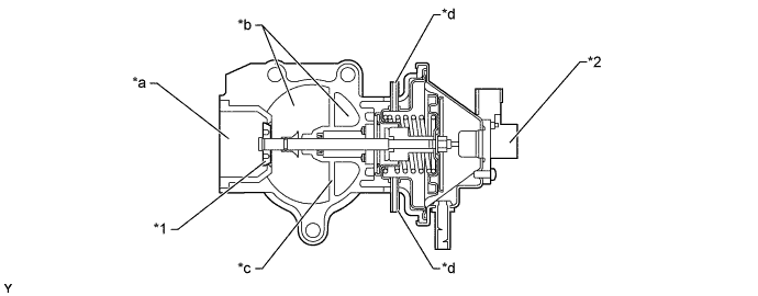
Text in Illustration *1 Outward-opening Type Valve *2 EGR Valve Position Sensor *a EGR Gas Inlet *b Intake Air Passage *c Intake Air Passage Partition *d Vacuum Port
-
-
EGR Valve (for Singapore)
-
An EGR valve is provided in the midstream of the intake air passage. By cooling the EGR valve in this manner, a greater volume of exhaust gas can be processed.
-
A vacuum port for a VSV (for EGR valve close) to cut off EGR is used to improve valve closure response.
-
An EGR valve position sensor has been provided in the EGR valve in order to directly measure the actual amount of the valve opening. This measurement is then input into the engine ECU in order to improve the precision of EGR control.
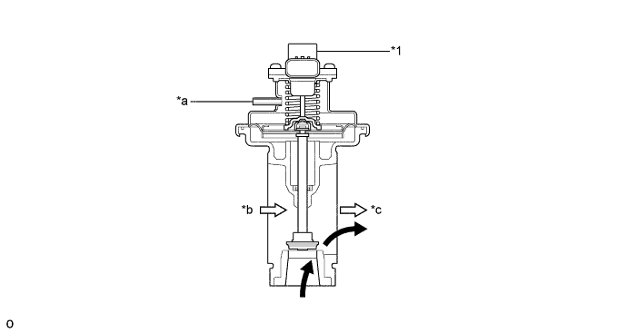
Text in Illustration *1 EGR Valve Position Sensor - - *a Vacuum Port *b from Air Cleaner *c to Intake Manifold - - 
EGR Gas 
Intake Air
-
-
EGR Cooler (for Europe)
-
A large capacity layered type EGR cooler has been adopted to improve the EGR gas cooling efficiency. In this way, the EGR volume has been increased, the temperature of the intake air during EGR operation is controlled, and the volume of NOx emissions has been significantly reduced, ensuring improved emission reduction efficiency.
-
An EGR cooler bypass switching valve which opens or closes the gas route to the EGR cooler in accordance with the running conditions of the engine is provided. This has led to the stabilization of the temperature of the EGR gas, and ensures stable emission reduction efficiency for a variety of running conditions.
-
By making the gas route of the EGR cooler a U-shape, both improved cooling efficiency, due to its increased capacity, and better use of space have been realized.
-
The main body section of the EGR cooler contains 2 sets of 5-layered heat transfer tubes (10 in total), and the EGR gas that flows through these heat transfer tubes is cooled by the surrounding coolant. By installing wavy shaped fins inside the heat transfer tubes, the cooling efficiency has been improved, and the EGR cooler has become more lightweight and compact.
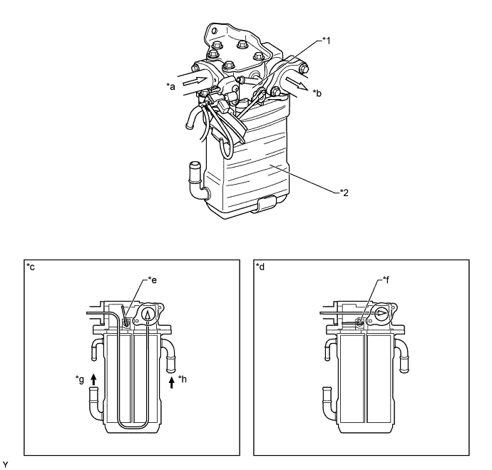
Text in Illustration *1 EGR Cooler Bypass Switching Valve *2 EGR Cooler *a EGR Gas Inlet (from Cylinder Head) *b EGR Gas Outlet (to EGR Valve) *c When the EGR Gas Needs to be Cooled *d When the EGR Gas Does Not Need to be Cooled *e Bypass Switching Valve (Closed) *f Bypass Switching Valve (Open) *g SLLC Outlet *h SLLC Inlet SLLC EGR Gas
-
-
EGR Cooler (for Singapore)
-
A water-cooled type EGR cooler is used. That lowers the exhaust gas temperature to recirculate the great amount of exhaust gas, realizing the reduction of NOx.
-
The EGR cooler is comprised of the six-layered heat exchanger tube, which contains the inner fins inside.
-
The inner fins have a wavy shape to enhance cooling efficiency and prevent them from becoming clogged with carbon deposits. The water flows around the heat exchanger tubes to cool down the exhaust gas.
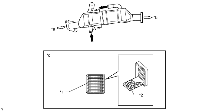
Text in Illustration *1 Heat Exchanger Tube *2 Inner Fin (Wavy Shaped) *a from Cylinder Head *b to EGR Valve *c A-A Cross Section - - Water Exhaust Gas
-
-