FUEL SYSTEM DETAILS
-
FUNCTION OF MAIN COMPONENTS
-
Supply Pump
Components Function Feed Pump Pumps fuel to two plungers. Regulator Valve Regulates fuel pressure in pump. Suction Control Valve Controls volume of fuel drawn in to plungers. Pump Body Eccentric Cam Drives ring cam. Ring Cam Drives two plungers. Plunger Effects suction and pumping of fuel. Delivery Valve Pumps fuel to common-rail.
-
-
CONSTRUCTION
-
Supply Pump
-
The supply pump mainly consists of a pump body (eccentric cam, ring cam, two plungers) SCV, fuel temperature sensor, and a feed pump.
-
The 2 plungers in the pump body are placed opposite each other outside of the ring cam.
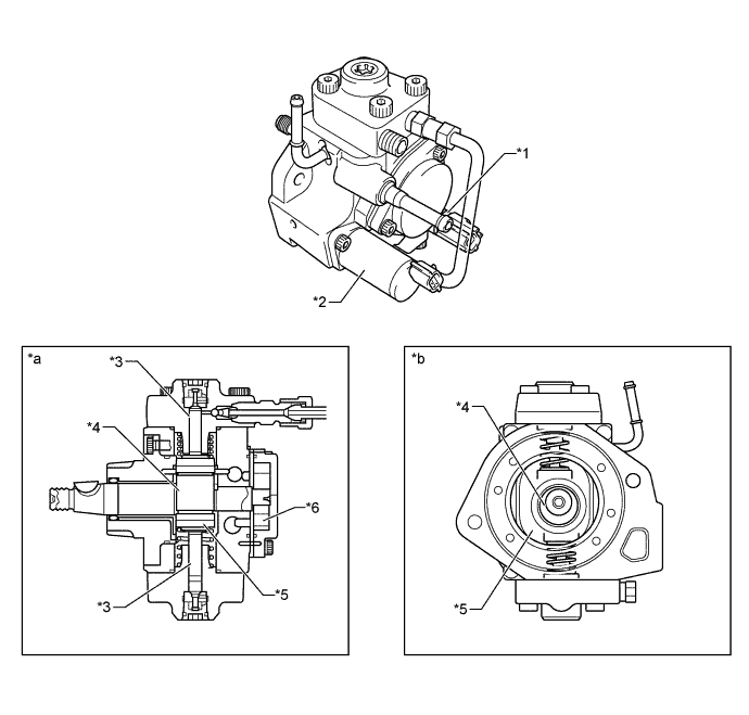
Text in Illustration *1 Fuel Temp. Sensor *2 SCV *3 Plunger *4 Eccentric Cam *5 Ring Cam *6 Feed Pump *a Side Cross Section *b Front Cross Section
-
-
Common-Rail
-
By storing fuel at a high pressure (30 to 135 MPa), the driving torque during the pumping of the fuel under high load conditions has been restrained, thus reducing the vibration and noise of the fuel injection system.
-
The fuel pressure sensor outputs the signal to the engine ECU.
-
When the pressure in the common-rail is abnormally high, the pressure limiter leaks the fuel to the fuel tank to reduce pressure.
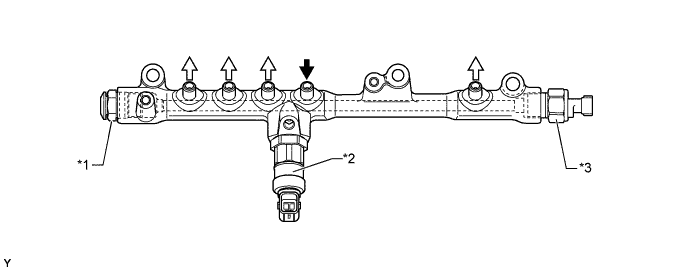
Text in Illustration *1 Pressure Limiter *2 Pressure Discharge Valve *3 Fuel Pressure Sensor - - 
from Supply Pump 
to Injector Tech Tips
-
Fuel pressure sensor has its sealing portion plastic-deformed in order to keep sealing performance, so do not reuse it after disassembling.
-
Do not disassemble the pressure limiter and pressure discharge valve because its operating pressure has been adjusted after assembly.
-
If parts that affect the alignment has been changed, make sure to replace the pipe with a new one as well. The parts that require the replacement of a pipe are listed below.
-
Injection Pipe: Injector, Common-Rail, Cylinder Head
-
Fuel Inlet Pipe: Supply Pump, Common-Rail, Cylinder Block, Water Pump, Cylinder Head
-
For details, refer to the Repair Manual.
-
-
-
Injector
-
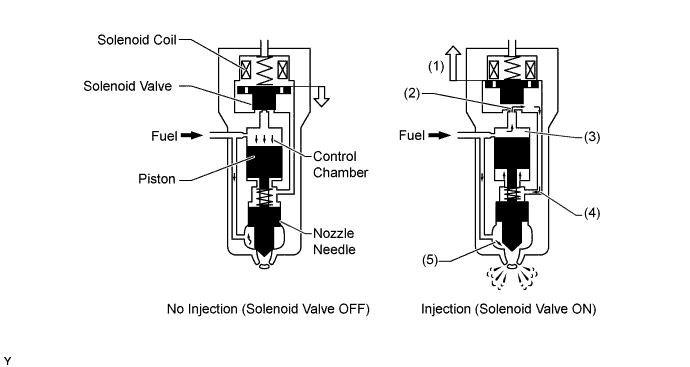
An injector consists of a nozzle needle, piston and solenoid valve.
-
High voltage (125 V) is used particularly when the valve is open in order to open the nozzle needle.
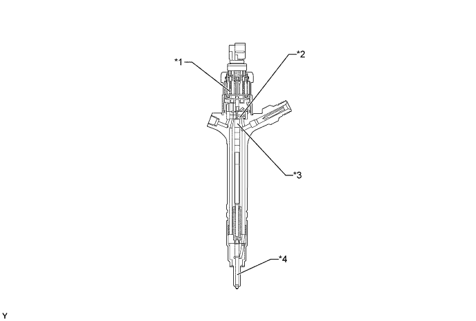
Text in Illustration *1 Solenoid Valve *2 Control Chamber *3 Piston *4 Nozzle Needle
-
-
-
OPERATION
-
Supply Pump
-
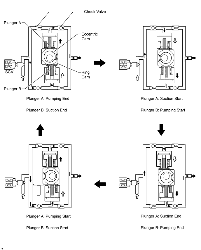
Due to the rotation of the eccentric cam, the ring cam pushes plunger A upward as illustrated below. The force of the spring pulls plunger B (which is located opposite plunger A) upward. As a result, plunger B draws fuel in, and plunger A pumps fuel at the same time.
-
The engine ECU controls the opening of the SCV in order to regulate the volume of fuel that is pumped by the supply pump to the common-rail. Consequently, the fuel pressure in the common-rail is controlled to the target injection pressure.
-
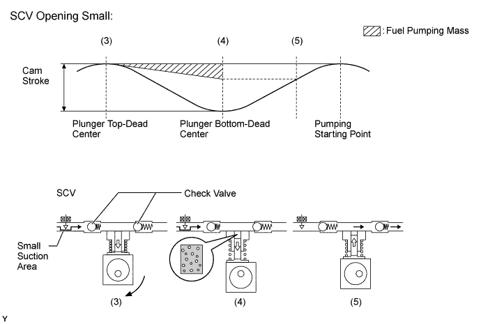
When the opening of the SCV is small, the fuel suction area is kept small, which decrease the transferable fuel quantity.
-
The plunger strokes fully, however, the suction volume becomes small due to the small suction area. Therefore, the difference of the volume between the geometry volume and the suction volume is in vacuum condition.
-
Pumping will start at the time when the fuel pressure has become higher than the common-rail pressure.
-
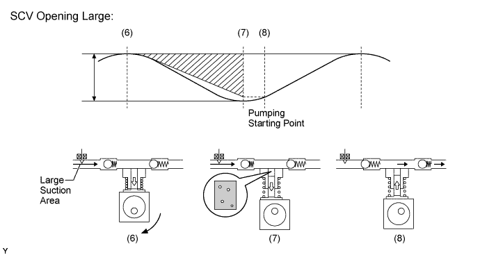
When the opening of the SCV is large, the fuel suction area is kept large, which increase the transferable fuel quantity.
-
If the plunger strokes fully, the suction volume will increase because the suction area is large.
-
Pumping will start at the time when the fuel pressure has become higher than the common-rail pressure.
-
When the fuel pressure in the common-rail becomes higher than the target injection pressure, the engine ECU discharges the fuel by way of the pressure discharge valve in order to control the fuel pressure to the target injection pressure.
Text in Illustration *1 Pressure Discharge Valve - - to Fuel Tank from Common-rail
-
-
Injector
-
When electrical current is applied to the solenoid coil, it pulls the solenoid valve up.
-
The orifice of the control chamber opens, allowing the fuel to flow out.
-
The fuel pressure in the control chamber drops.
-
Simultaneously, fuel flows from the orifice to the bottom of the piston and raises the piston up (to enhance response).
-
As a result, the piston raises the nozzle needle to inject fuel.
-
-