FUEL SYSTEM DETAILS
-
FUNCTION OF MAIN COMPONENTS
-
Supply Pump
Components Function Feed Pump Pumps fuel to 2 plungers. Regulator Valve Regulates fuel pressure in pump. Suction Control Valve Controls volume of fuel drawn in to plungers. Pump Body Eccentric Cam Drives ring cam. Ring Cam Drives 2 plungers. Plunger Effects suction and pumping of fuel. Delivery Valve Pumps fuel to common-rail.
-
-
SYSTEM CONTROL
-
Common-rail System
-
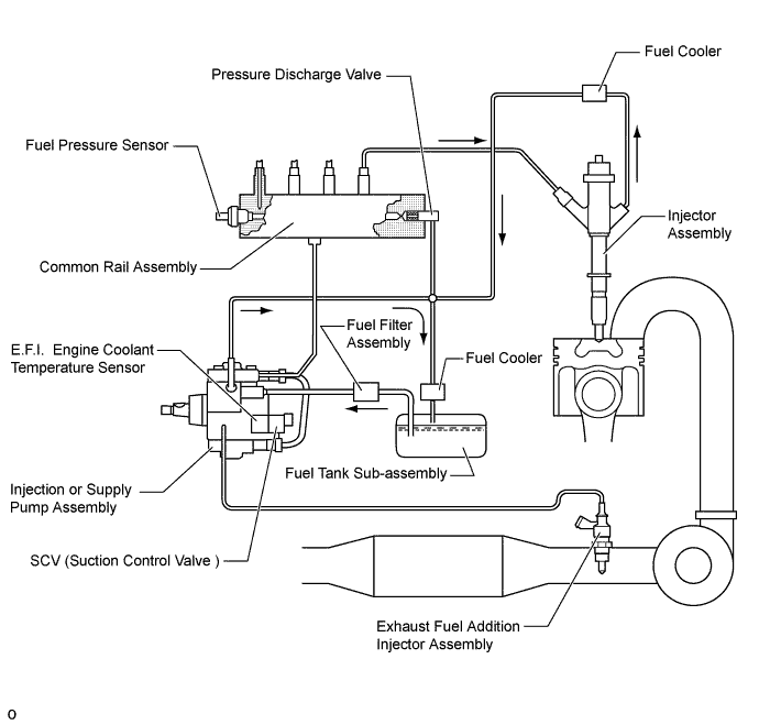
In this system, the high-pressurized fuel that is supplied by the injection or supply pump assembly is stored in the common rail assembly, and the ECM sends signals to the injectors via the injector driver in order to control the injection timing and injection volume.
-
Fuel pressure is controlled in accordance with fuel pumping volume that is controlled by the SCV (Suction Control Valve) in the injection or supply pump assembly and fuel discharge volume that is controlled by the pressure discharge valve in order to realize accurate fuel pressure control. The SCV (Suction Control Valve) and pressure discharge valve are controlled by the ECM via the injector driver.
-
-
-
CONSTRUCTION
-
Supply Pump
-
The injection or supply pump assembly consists of an eccentric camshaft, a ring cam, 2 plungers, 4 check valves, SCV (Suction Control Valve), a fuel gas temperature sensor and a feed pump.
-
The 2 plungers are placed opposite to each other outside of the ring cam.
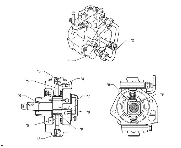
Text in Illustration *1 SCV (Suction Control Valve) *2 Fuel Gas Temperature Sensor *3 Check Valve (for Suction) *4 Check Valve (for Discharge) *5 Plunger *6 Eccentric Camshaft *7 Feed Pump *8 Eccentric Cam Portion *9 Ring Cam - - Tech Tips
-
The ECM learns and memorizes the pump discharge volume variances associated with the individual differences in the injection or supply pump assembly. Therefore, make sure to perform the operation described below after replacing the injection or supply pump assembly. For details, refer to the Repair Manual.
-
Connect an intelligent tester II to the DLC3 connector and use the tester to reset the learned value.
-
Alternatively, connect the SST (09843-18040) to the TC and CG terminals of the DLC3 connector, and leave the ignition switch ON for approximately 3 minutes to reset the learned value.
-
After resetting, start the engine, allow it to idle* for approximately 1 minute, and turn the ignition switch OFF to enable the engine to memorize the learned value.
-
*: The engine coolant temperature should be 60°C (140°F) or more, and the fuel temperature should be 20°C (68°F) or more.
-
-
-
Common-Rail
-
The function of the common rail assembly is to store the fuel that has been pressurized by the injection or supply pump assembly. The common rail assembly is equipped with a fuel pressure sensor, which detects the fuel pressure in the common rail assembly, and a pressure discharge valve, which regulates the fuel pressure.
-
Internally, the common rail assembly contains a main hole and 5 branch holes that intersect the main hole. Each branch hole functions as an orifice that dampens the fluctuation of the fuel pressure.
-
In the pressure discharge valve, the plunger opens and closes in accordance with the actuation signals from the injector driver. Thus, it regulates pressure by releasing excess pressure from the common rail assembly. In addition, it has a pressure reduction function in case of emergency.
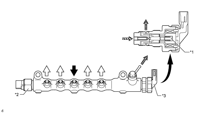
Text in Illustration *1 Plunger *2 Fuel Pressure Sensor *3 Pressure Discharge Valve - - 
Fuel Inlet 
Fuel Outlet 
from Common Rail Assembly (High Pressure) 
to Fuel Tank Sub-Assembly (Excess Pressure) Tech Tips
-
Fuel pressure sensor has its sealing portion plastic-deformed in order to keep sealing performance, so do not reuse it after disassembling.
-
If parts that affect the alignment has been changed, make sure to replace the pipe with a new one as well. The parts that require the replacement of a pipe are listed below.
-
Injection Pipe: injector, common rail assembly, cylinder head sub-assembly
-
Fuel Inlet Pipe: injection or supply pump assembly, common rail assembly, cylinder block sub-assembly, engine water pump assembly, cylinder head sub-assembly
-
For details, refer to the Repair Manual.
-
-
-
Injector
-
A fuel injector consists of the following components; a piezo actuator that controls inward or outward fuels, a displacement amplifier that amplifies the amount of the actuator operation, a 3-way valve that controls a nozzle needle, that opens and closes the fuel spray orifice.
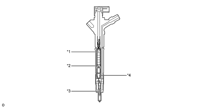
Text in Illustration *1 Piezo Actuator *2 Amplifier Piston *3 Nozzle Needle *4 3-way Valve
-
-
Fuel Filter
-
A fuel filter assembly consists of a fuel filter element integrated with the fuel filter housing.
-
Either a fuel filter assembly with fuel heater or a fuel filter assembly without fuel heater is available depending on the specifications.
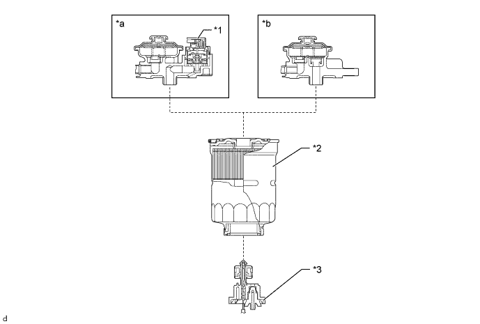
Text in Illustration *1 Fuel Heater Assembly *2
-
Fuel Filter Assembly
-
Filter Element
*3 Level Warning Switch - - *a with Heater Type *b without Heater Type -
-
-
Fuel Cooler
-
The fuel cooler of the air cooled type is used. The fuel coolers, which are provided in the fuel return path, cool the return fuel that has reached a high temperature as a result of the pumping of the injection or supply pump assembly. This prevents the reduction in fuel viscosity that is caused by the rise in fuel temperature, and improves the reliability of the fuel system.
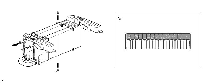
Text in Illustration *a A-A Cross Section - - to Fuel Tank Sub-assembly from Engine
-
-
-
OPERATION
-
Supply Pump
-
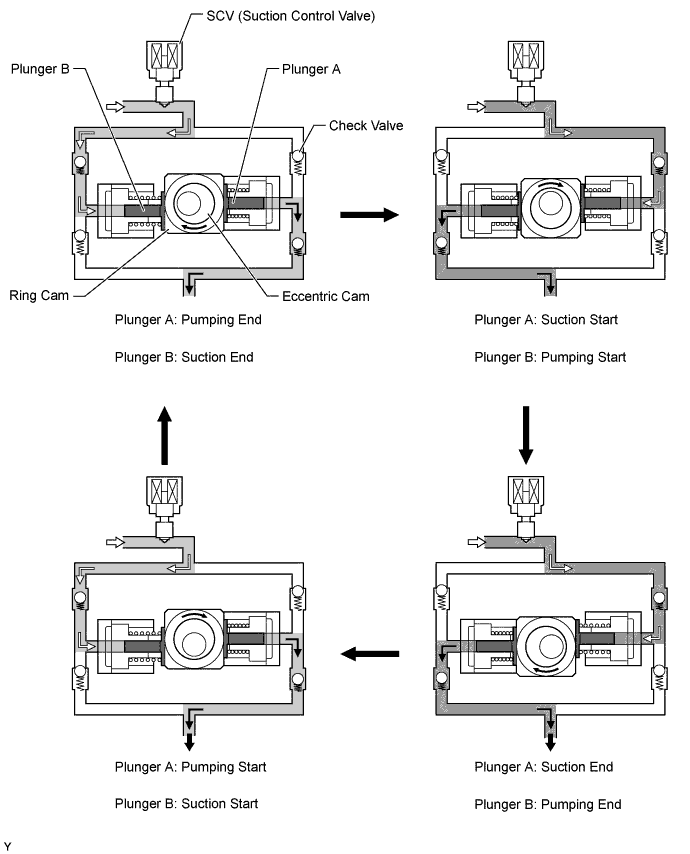
Due to the rotation of the eccentric cam, the ring cam pushes plunger A upward as illustrated below. The force of the spring pulls plunger B (which is located opposite plunger A) downward. As a result, plunger B draws fuel in, and plunger A pumps fuel at the same time.
-
The SCV (Suction Control Valve) controls the volume of fuel that is drawn into the plungers in accordance with the signals from the ECM.
-
-
Injector
-
When current is applied to the piezo actuator, the No. 1 piston, No. 2 piston and 3-way valve are pushed down.
-
The orifice on the upper part of the 3-way valve opens and the fuel in the control chamber flows out.
-
The fuel pressure in the control chamber drops.
-
Current to the piezo actuator is shut off and the No. 1 and No. 2 pistons and the 3-way valve are pushed up due to spring tension.
-
The orifice on the upper part of the 3-way valve closes to stop fuel flow.
-
The fuel pressure in the control chamber rises.
-
As a result, the nozzle needle goes down to stop fuel injection.
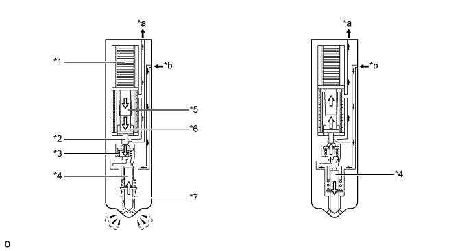
Text in Illustration *1 Piezo Actuator *2 Orifice *3 3-way Valve *4 Control Chamber *5 No. 1 Piston *6 No. 2 Piston *7 Nozzle Needle - - *a Return Fuel *b Fuel from Common Rail Assembly
-
-
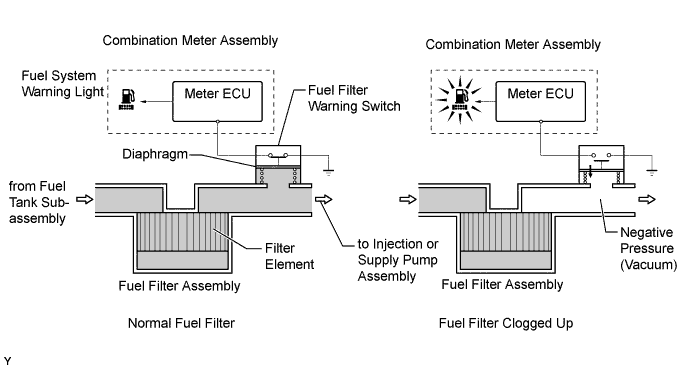
Fuel Filter Warning Switch (for Singapore)
-
A fuel filter warning switch, which turns ON/OFF when the internal vacuum of the fuel filter assembly increases, is provided in the fuel filter assembly. This switch, which turns OFF when the internal vacuum of the fuel filter assembly increases to a predetermined level, is connected by wire to the meter ECU.
-
When the meter ECU detects that the internal vacuum of the fuel filter assembly has increased (by way of the fuel filter warning switch OFF signal), it determines that the fuel filter assembly has become clogged. Then, it illuminates the fuel system warning light on the combination meter to urge the driver to replace the fuel filter assembly.
-
-