ECD SYSTEM DETAILS
-
FUNCTION OF MAIN COMPONENTS
-
The main components of the 1KD-FTV engine control system are as follows:
Components Outline Quantity Function ECM 32-bit CPU 1 The ECM effects overall control of the engine control system to suit the operating conditions of the engine in accordance with the signals provided by the sensors. Injector Driver DC/DC Converter 1 The injector driver is used to drive the injector at high speeds. The injector driver has realized high-speed driving under high fuel pressure conditions through the use of a DC/DC converter that provides a high voltage, quick-charging system. Turbo Pressure Sensor Semiconductor Silicon Chip Type 1 This sensor uses built-in semiconductors to detect the intake manifold pressure. Atmospheric Pressure Sensor Semiconductor Silicon Chip Type 1 This sensor, which is built into the ECM, uses semiconductors to detect the atmospheric pressure. Fuel Pressure Sensor Semiconductor Strain Gauge Type 1 This sensor uses built-in semiconductors to detect the internal pressure of the common rail assembly. Crank Position Sensor Pick-up Coil Type (Rotor Teeth/36-2) 1 This sensor detects the engine speed and performs the cylinder identification. No. 2 Crank Position Sensor (Camshaft Position Sensor) Pick-up Coil Type (Rotor Teeth/5) 1 This sensor performs the cylinder identification. Intake Mass Air Flow Meter Assembly Hot-wire Type 1 This sensor uses a built-in hot-wire to directly detect the intake air mass and flow rate. Atmospheric Temperature Sensor Thermistor Type 1
-
This sensor, which is provided at the air cleaner outlet, detects the intake air temperature by means of an internal thermistor.
-
This sensor is built into the air flow meter.
E.F.I. Engine Coolant Temperature Sensor Thermistor Type 1 This sensor detects the water temperature by means of an internal thermistor. Diesel Turbo Inlet Air Temperature Sensor Thermistor Type 1 This sensor detects the intake air temperature after the intercooler. Fuel Gas Temperature Sensor Thermistor Type 1 This sensor detects the fuel temperature in the injection or supply pump assembly by means of an internal thermistor. Throttle Position Sensor Non-contact Type 1 This sensor detects the throttle valve opening angle. Nozzle Vane Position Sensor Non-contact Type 1 This sensor detects the nozzle vane position. Accelerator Pedal Position Sensor Non-contact Type 1 This sensor detects the amount of pedal effort applied to the accelerator pedal. EGR Valve Position Sensor Non-contact Type 1 This sensor detects the actual amount of the EGR valve opening. Differential Pressure Sensor Assembly Semiconductor Strain Gauge Type 1 The differential pressure sensor assembly measures the pressure difference between front and back of the DPF catalyst with PM in order to detect the occurrence of clogging. Exhaust Gas Temperature Sensor Thermistor Type 3 This sensor detects the temperature of the exhaust gas. Air Fuel Ratio Sensor Planar Type with Heater 1 The air fuel ratio sensor data is approximately proportional to the existing air fuel ratio. The air fuel ratio sensor converts the oxygen density to the current and sends it to the ECM. SCV (Suction Control Valve) Linear Solenoid Valve 1 The SCV (Suction Control Valve) position is controlled by the signals from the ECM, and a fuel volume that suits the SCV (Suction Control Valve) position is drawn into the pumping portion (plunger portion). Injector Assembly 10-hole Piezo Type 4 The fuel injector assembly is an electromagnetically-operated solenoid with a nozzle which injects fuel in accordance with signals from the ECM. Exhaust Fuel Addition Injector Assembly Solenoid Type 1 To reduce PM, the ECM controls the injection timing and the injection frequency of the injectors, and activates the exhaust fuel addition injector assembly. Clutch Switch Assembly One condition for fuel injection volume correction 1 The clutch switch assembly detects the operation of the clutch pedal. Oil Pressure Switching Valve Solenoid Type 1 The oil pressure switching valve controls the engine oil pressure in accordance with signals from the ECM. -
-
-
SYSTEM CONTROL
-
The engine control system of the 1KD-FTV engine has the following system.
System Outline Fuel Injection Volume Control Based on the signals received from the sensors, the ECM determines the fuel injection volume in accordance with the engine condition. It also corrects the injection volume for each injector, based on the signals input from the crank position sensor and the clutch switch assembly, etc. Fuel Injection Timing Control Based on the signals received from the sensors, the ECM determines the fuel injection timing in accordance with the engine condition. Fuel Pressure Control Based on the signals received from the sensors, the ECM controls fuel pressure using the SCV (Suction Control Valve) and pressure discharge valve according to the engine condition. Pilot Injection Control Based on the signals received from the sensors, the ECM determines pilot injection volume/timing, and interval (between pilot injection and main injection) in accordance with the engine condition. During Starting Control To facilitate startability, the ECM optimally controls the injection volume and injection timing during starting. Idle Speed Control The ECM determines the idle speed in accordance with the engine condition, and controls the fuel injection volume in order to maintain the target idle speed. Glow Plug Control Using the glow plug controller, the energization timings for each glow plug assembly are adjusted separately. Throttle Control Based on the signals received from the various sensors, the ECM determines throttle valve position in accordance with the engine condition. Fully close the throttle valve in order to reduce the vibration when the engine is stopped. Swirl Control Based on the signal received from the sensors, the ECM controls the vacuum to 3-stage using 2 VSVs. Turbocharger Control Based on the signals received from the sensors, the ECM controls the actuator in accordance with the engine condition. Catalyst Support Control Based on the signals received from the sensors, the ECM controls the exhaust fuel addition injector assembly to reduce the PM. EGR Control Based on the signals received from the sensors, the ECM determines the EGR volume using the DC motor type EGR valve assembly and No. 2 vacuum switching valve assembly in accordance with the engine condition. Air-fuel Ratio Sensor Heater Control The ECM regulates the charging voltage of the alternator in accordance with the driving conditions. Oil Pressure Control System The ECM controls the engine oil pressure in 2 stages to reduce friction losses. Oil Maintenance Management System* When the ECM detects engine oil and oil filter deterioration, the engine oil change reminder light informs the driver of the need to replace them, using the 2-step illumination method. Brake Override System The driving torque is restricted when the brake pedal is depressed while the accelerator pedal is depressed. (For the activation conditions and inspection method, refer to the repair manual) Diagnosis When the ECM detects a malfunction, the ECM diagnoses and memorizes the failed section. Fail-safe When the ECM detects a malfunction, the ECM stops or controls the engine according to the data already stored in the memory.
-
*: Models for Europe
-
-
-
FUNCTION
-
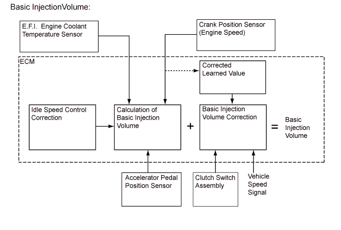
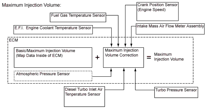
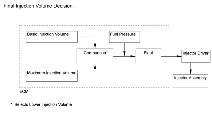
Fuel Injection Volume Control
-
Small injection volume correction control is a type of control, performed for pilot injection volume, etc., that detects the change in the engine speed when the ECM outputs a small injection volume instruction, and determines the differences between the injection instruction and the actual injection volume for each injector.
-
Extensive intra-cylinder injection volume correction control is a type of control, performed for each injector, whereby the ECM detects the combustion status of each cylinder based on the signals from the crank position sensor to balance the torque generated by each cylinder.
Tech Tips
-
As the learned values for the small injection volume correction of each injector assembly are stored in the ECM, it will be necessary for the small injection volume correction values to be relearned or for the learned values to be read or rewritten when the injectors (and engine assembly) or the ECM is replaced. For details, refer to the Repair Manual.
-
As the ECM corrects the NE signals (engine speed signals) sent from the crank position sensor and stores them as learned values before performing extensive intra-cylinder injection volume correction, it will be necessary for the extensive intra-cylinder injection volume correction values to be reset or for the learned values to be read or rewritten when the crankshaft position rotor (and engine assembly) or the ECM is replaced. If these operations are not carried out after the corresponding parts are replaced, there is the possibility that engine vibration will be generated. For details, refer to the Repair Manual.
-
-
-
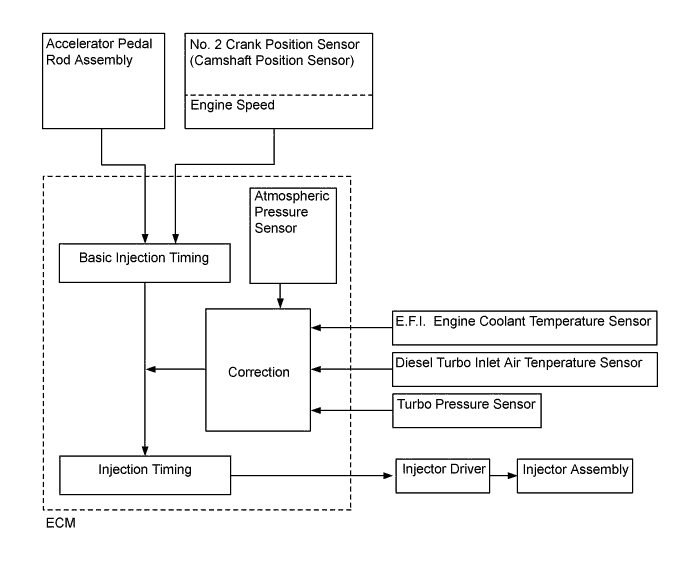
Fuel Injection Timing Control
-
Fuel injection timing is controlled as shown below.
-
-
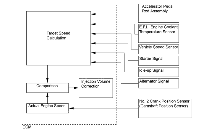
Idle Speed Control
-
Fuel injection timing is controlled as shown below.
-
-
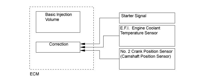
During Starting Control (Injection Volume Control)
-
The starting injection volume is determined by adjusting the basic injection volume in accordance with the starter ON signals (ON time), E.F.I. engine coolant temperature sensor signals and engine speed signal. When the engine is cold, the water temperature will be lower and the injection volume will be greater.
-
-
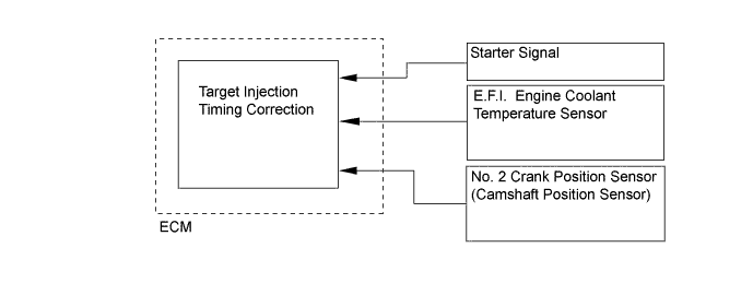
During Starting Control (Injection Timing Control)
-
To determine the starting injection timing, the target injection timing is corrected in accordance with the starter signals, water temperature and engine speed. When the water temperature is low, if the engine speed is high, the injection timing is advanced.
-
-
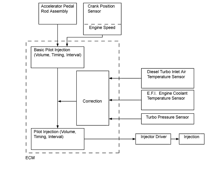
Pilot Injection Control
-
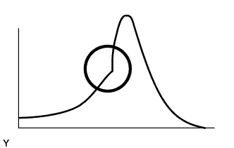
Pilot injection is a method that provides auxiliary fuel injection before the main injection takes place. The purpose of pilot injection is to gently start the combustion of the fuel of the main injection in order to reduce combustion noise.
State Pilot Injection Ordinarily Injection Fuel Injection 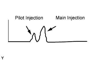
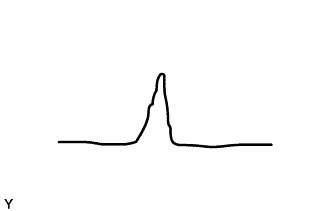
Combustion Pressure 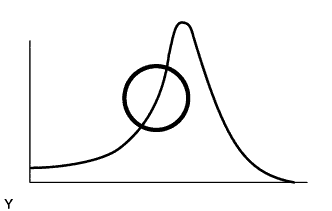
-
During pilot injection, the pilot injection volume, timing, and interval (between pilot injection and main injection) are controlled as shown below.
-
-
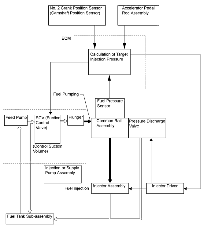
Fuel Pressure Control
-
ECM calculates the target injection pressure (25-180 MPa) based on the engine conditions which are the signals from the accelerator pedal rod assembly and the crank position sensor. To control fuel pressure, signals sent to SCV (Suction Control Valve) of the injection or supply pump assembly regulate the suction volume and signals sent to pressure discharge valve of the common rail assembly regulate the discharge volume, so that the pressure detected by the fuel pressure sensor matches the target injection pressure.
-
-
Oil Maintenance Management System (for Europe)
-
An oil maintenance management system is used. This system determines the deterioration condition of the engine oil and illuminates an engine oil change reminder light to inform the driver when the engine oil and oil filter must be changed. Accordingly, the maintenance intervals (30,000 km maximum) that correspond to the actual deterioration conditions of the engine oil have been realized.
-
The accumulated soot volume and kilometrage/mileage memorized in the meter ECU can be reset using the following procedure.
-
Turn the ignition or starter switch assembly to ON. Then switch the ODO/TRIP meter (LCD) to "TRIP A" mode, using the ODO/TRIP switch.
-
Turn the ignition or starter switch assembly off. Then turn it to ON while pressing the ODO/TRIP switch.
-
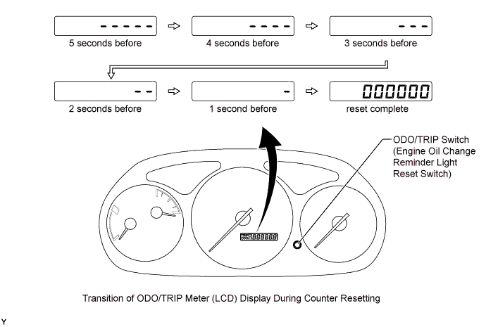
After turning the ignition or starter switch assembly to ON, press and hold the ODO/TRIP switch (for at least 5 seconds) with the ODO/TRIP meter counting down as shown below.
-
The resetting procedure is complete when the ODO/TRIP meter (LCD) has returned to "TRIP A" mode, after displaying "000000" for approximately 1 second, and the engine oil change reminder light has gone off.
Tech Tips
A function which causes the engine oil change reminder light to blink at a frequency of 1.0 Hz if there is a communication abnormality or disconnection of the communication line between the ECM and the meter ECU has been incorporated into the meter ECU.
-
-
-
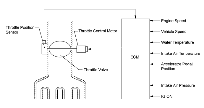
Throttle Control
-
The opening of the throttle valve is controlled by the ECM in accordance with engine conditions. As a result, the noise that is generated during idling and deceleration, as well as the noise and vibration that are generated when the engine is stopped, have been reduced.
-
-
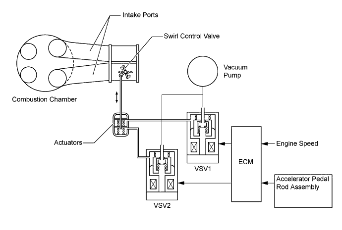
Swirl Control
-
The ECM determines the swirl control valve opening angle (fully open, half open or fully closed) in accordance with the engine conditions (such as engine speeds, accelerator pedal angles), and changes the vacuum applied to the diaphragm of the vacuum actuator via the 2 VSV, operating the swirl control valve.
-
In order to deliver stable combustion, the ECM regulates the air-fuel mixture ratio by controlling the swirl control valves in a manner corresponding to the engine speed range as follows; when the engine speed is in the low range, the ECM closes the valves to boost the swirl developed inside the cylinder, and in the middle range, it half opens the valve.
-
-
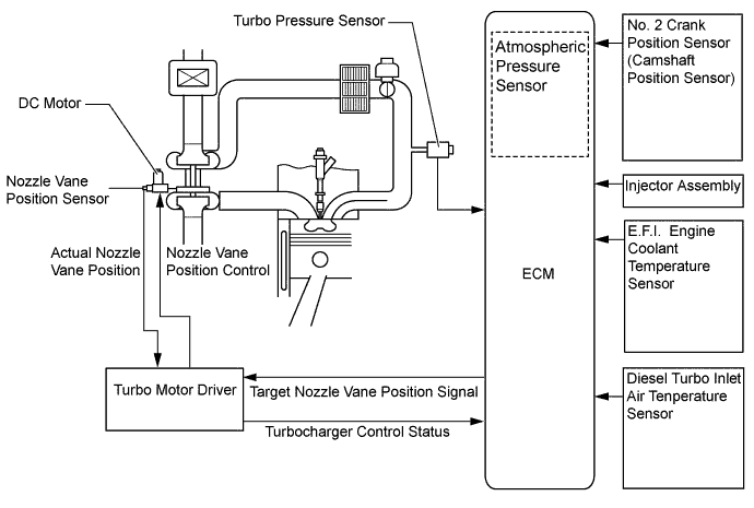
Turbocharger Control
-
The ECM controls the nozzle vane position using the turbo motor driver, in order to obtain the calculated target turbo pressure appropriate to the engine operating condition.
-
The ECM calculates the optimal nozzle vane position in accordance with the driving conditions (engine speed, injection volume, atmospheric pressure, water temperature, etc.), and sends a target nozzle vane position signal to the turbo motor driver. The turbo motor driver controls the nozzle vane position in accordance with this signal and the actual nozzle vane position signal provided by the nozzle vane position sensor.
-
-
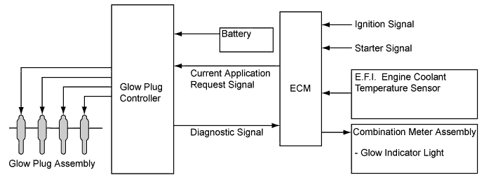
Glow Plug Control
-
The glow plug controller manages the cylinder glow plug assembly energization timings according to signals from the ECM so as to equalize all the energization time periods. The glow plug controller has a function to detect open circuits in the glow plugs. When the glow plug controller detects an open circuit in a glow plug assembly, it sends a signal to the ECM.
-
-
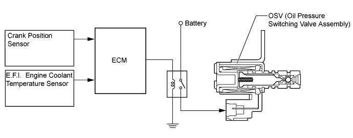
Oil Pressure Control
-
The ECM controls the OSV (Oil Pressure Switching Valve Assembly) of the electric variable oil pressure type oil pump in accordance with water temperature, engine speed and fuel injection volume to regulate the engine oil pressure in 2 stages.
-
-
-
CONSTRUCTION
-
Air Flow Meter
-
The intake mass air flow meter assembly of diesel engine uses precise fuel injection volume control and EGR control to realize clean emission.
-
The plug-in type air flow meter is used, and this allows a portion of the intake mass air flow meter assembly through the detection area. By directly measuring the mass and the flow rate of the intake air, the detection precision is ensured and the intake air resistance is reduced.
-
The intake mass air flow meter assembly has a built-in atmospheric temperature sensor.

Text in Illustration *1 Temperature Sensing Element *2 Hot-wire Element *3 Atmospheric Temperature Sensor - - 
Air Flow - -
-
-
Fuel Pressure Sensor
-
The fuel pressure sensor, which is mounted on the common rail assembly, outputs a signal that represents the fuel pressure in the common rail assembly to the ECM in order to constantly regulate the fuel at an optimal pressure.
-
The fuel pressure sensor contains 2 circuits (Main and Sub), which enable the ECM to constantly compare the values detected by the 2 circuits. As a result, highly precise values can be detected, which also enable a higher level of fail-safe control.
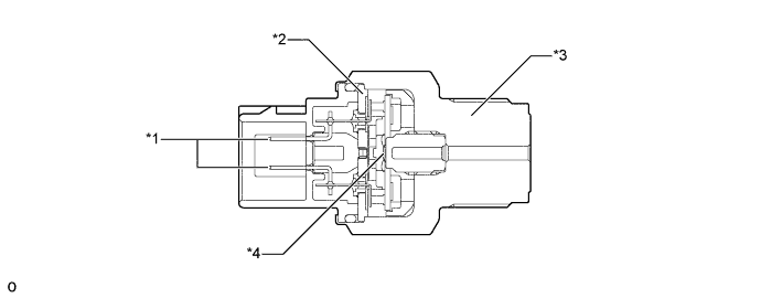
Text in Illustration *1 Terminal *2 Capacitor *3 Sensor Module *4 Pressure Detecting Portion 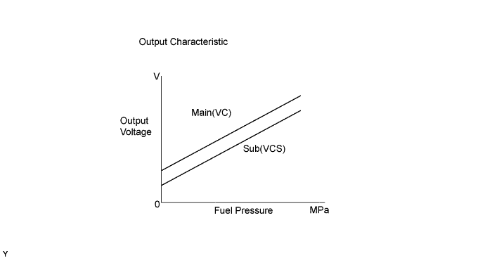
-
-
Turbo Pressure Sensor
-
The turbo pressure sensor consists of a semiconductor which utilizes the characteristic of a silicon chip that changes its electrical resistance when pressure is applied to it. The sensor converts the intake air pressure into an electrical signal, and sends it to the ECM in an amplified form.
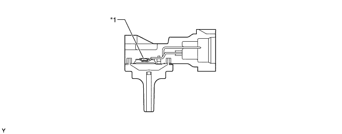
Text in Illustration *1 Sensor Unit - - 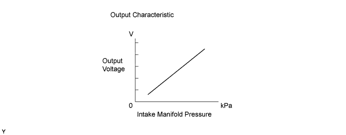
-
-
Crankshaft Position Sensor and Camshaft Position Sensor
-
The timing rotor of the crankshaft consists of 34 teeth, with 2 teeth missing. The crank position sensor outputs the crankshaft rotation signals every 10°, and the missing teeth are used to determine the top-dead-center.
-
To detect the camshaft position, a protrusion that is provided on the timing pulley is used to generate 5 pulses for every 2 revolutions of the crankshaft.
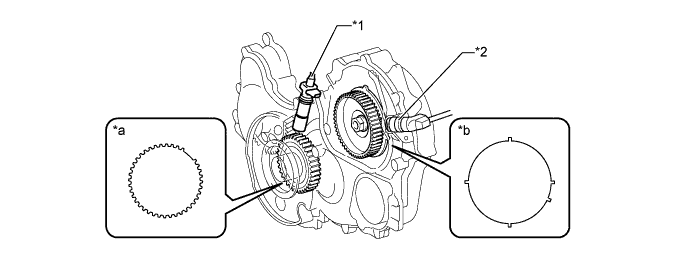
Text in Illustration *1 Crank Position Sensor *2 No. 2 Crank Position Sensor (Camshaft Position Sensor) *a 34 Pulse/360° CA *b 5 Pulse/720° CA 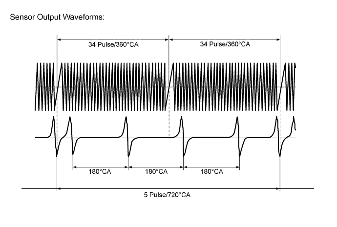
-
-
Accelerator Pedal Position Sensor
-
The non-contact type accelerator pedal rod assembly uses a Hall IC, which is mounted on the accelerator pedal arm.
-
The magnetic yoke that is mounted at the base of the accelerator pedal arm moves around the Hall IC in accordance with the amount of effort that is applied to the accelerator pedal. The Hall IC converts the changes in the magnetic flux that occur into electrical signals, and outputs them in the form of accelerator pedal position signals to the ECM.
-
The accelerator pedal rod assembly includes 2 Hall ICs and circuits for the main and sub signals. It converts the accelerator pedal depression angles into 2 electrical signals with differing characteristics and outputs them to the ECM.
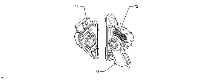
Text in Illustration *1 Hall IC *2 Magnetic Yoke *3 Accelerator Pedal Arm - - 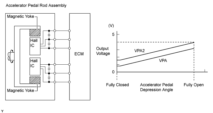
-
-
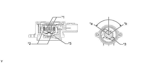
Throttle Position Sensor
-
The throttle position sensor is mounted on the throttle body with motor assembly, to detect the opening angle of the throttle valve. The throttle position sensor converts the magnetic flux density that changes when the magnetic yoke (located on the same axis as that of the throttle valve shaft) rotates around the Hall IC into electric signals to operate the throttle control motor.
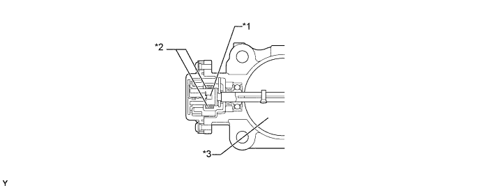
Text in Illustration *1 Hall IC *2 Magnetic Yoke *3 Throttle Valve - - 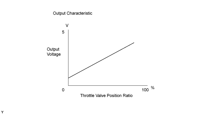
-
-
Nozzle Vane Position Sensor
-
The nozzle vane position sensor consists of a Hall IC and a magnetic yoke that rotates in unison with the movement of the linkage that actuates the nozzle vane. The nozzle vane position sensor converts the changes in the magnetic flux that are caused by the rotation of the DC motor (hence, the rotation of the magnetic yoke) into electric signals, and outputs them to the turbo motor driver. The turbo motor driver determines the actual nozzle vane position from the electric signals in order to calculate the target nozzle vane position.
Text in Illustration *1 Hall IC *2 Magnetic Yoke *3 Sensor Lever - - *a Full Close *b Full Open 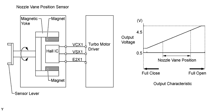
-
-
Oil Pressure Switching Valve
-
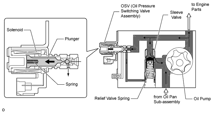
The oil pressure switching valve controls the engine oil pressure in accordance with signals from the ECM. The oil pressure switching valve assembly consists of a plunger, coil and spring.
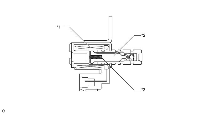
Text in Illustration *1 Solenoid *2 Plunger *3 Spring - -
-
-
-
OPERATION
-
Oil Maintenance Management System (for Europe)
-
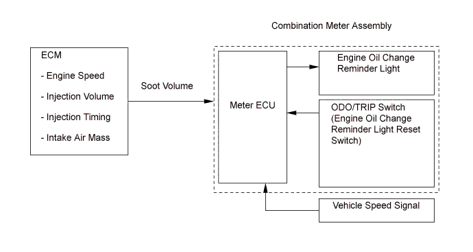
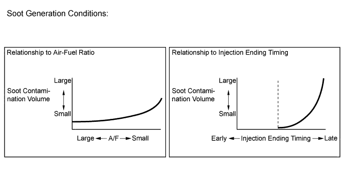
This system determines the deterioration of the engine oil in accordance with the soot volume in the engine oil.
-
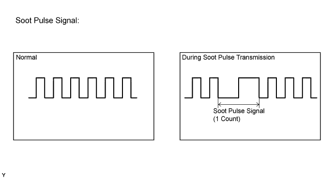
The ECM calculates the soot volume in the engine oil in accordance with the engine speed, injection timing, injection volume, and intake air mass. The ECM converts the soot volume into pulse signals and transmits the signals to the meter ECU.
-
When the distance traveled is approximately 25000 km (15000 miles): after the ignition switch has been turned to ON and the (warning and indication) light check has been performed (approximately 3 seconds), the engine oil change reminder light blinks for approximately 12 seconds at a frequency of 0.5 Hz, and then goes off.
-
When the distance traveled is approximately 30000 km (18000 miles): the engine oil change reminder light remains illuminated while the ignition switch is in the ON position.
-
Thus, this system informs the driver that the engine oil and oil filter must be changed.
-
If the accumulated soot volume reaches the specified value, there may be cases where the engine oil change reminder light blinks or illuminates, even if the distance traveled is 5000 km (3100 miles) or more.
Tech Tips
This system does not determine the deterioration of the engine oil based on the elapsed time. Even if the engine oil change reminder light does not illuminate, the engine oil and oil filter should be changed at 2-year intervals at the maximum.
-
-
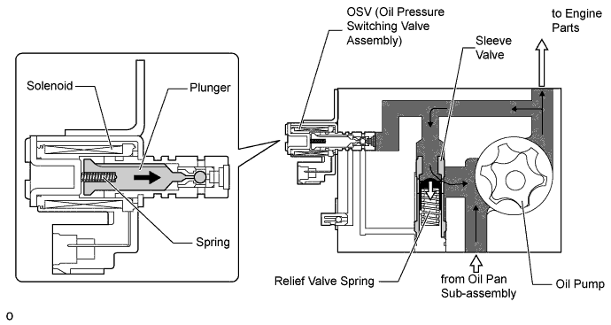
Oil Pressure Control
-
High Pressure Control
-
When the ECM turns the OSV (Oil Pressure Switching Valve Assembly) off, no oil pressure is applied to the lower portion of the sleeve valve. The oil pressure of the oil pump pushes the sleeve valve downward while compressing the relief valve spring together with the relief valve. Consequently, the oil passage provided on the side of the sleeve valve is moved downward as well. As a result, the opening pressure of the relief valve increases and the engine oil pressure is controlled to a high level.
-
-
Low Pressure Control
-
When the ECM turns the OSV (Oil Pressure Switching Valve Assembly) on, oil pressure is applied to the lower portion of the sleeve valve. This pushes the sleeve valve upward and moves the oil passage provided on the side of the sleeve valve upward also. At the same time, the relief valve is moved upward by the force of the relief valve spring. As a result, the opening pressure of the relief valve decreases and the engine oil pressure is controlled to a low level.
-
-
-
-
FAIL-SAFE
-
Fail-safe Operation
-
When a malfunction is detected by any of the sensors, there is a possibility of an engine or other malfunction occurring if the ECM were to continue to control the engine control system in the normal way. To prevent such a problem, the fail-safe function of the ECM either relies on the data stored in memory to allow the engine control system to continue operating, or stops the engine if a hazard is anticipated. For details, refer to the Repair Manual.
-
-
Fail-safe Operation due to Accelerator Pedal Position Sensor Malfunction
-
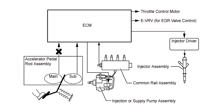
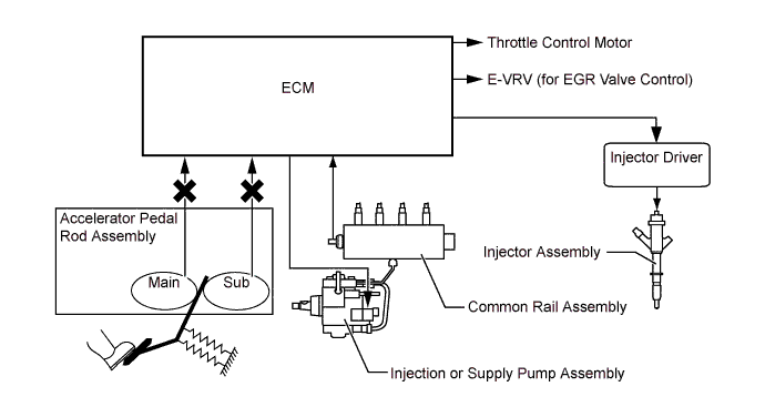
The accelerator pedal rod assembly contains 2 sensor circuits (Main, Sub). If the ECM detects an abnormality in either or both of the sensors, the mode switches to the accelerator opening angle restriction mode.
-
If a malfunction occurs in either of the sensor circuits, the ECM detects the abnormal signal voltage difference between these 2 sensor circuits and switches to a fail-safe mode. In this fail-safe mode, the remaining circuit is used to calculate the accelerator pedal opening, in order to operate the vehicle under fail-safe mode control.
-
If both circuits malfunction, the ECM detects the abnormal signal voltage from these 2 sensor circuits and discontinues throttle control. At this time, the vehicle can be driven using the power generated by the engine at idle speed.
-
-
-
DIAGNOSIS
-
The diagnosis system of the 1KD-FTV engine uses the EURO-OBD (EURO On-Board Diagnosis).
-
When the ECM detects a malfunction, the ECM makes a diagnosis and memorizes the failed section. Furthermore, the check engine warning light in the combination meter illuminates or blinks to inform the driver.
-
The ECM also stores the DTCs (Diagnostic Trouble Codes) of the malfunctions. The DTCs can be read by connecting the SST (09843-18040) to the TC and CG terminals of the DLC3, and observing the blinking of the check engine warning light (2-digit code), or by connecting the intelligent tester II to the DLC3 (5-digit code).
-
By using the intelligent tester II, the ECU data can be read out. Moreover, the ACTIVE TEST can be used to drive the actuator by means of the intelligent tester II.
-
The ECM can output freeze-frame data to the intelligent tester II. This data is stored in the ECM at the very moment when the ECM detects its last data of malfunction.
-
To clear the DTC that is stored in the ECM, use the intelligent tester II, and disconnect the battery terminal or remove the EFI fuse for 1 minute or longer.
-
For details, refer to the Repair Manual.
-