ENGINE UNIT DETAILS
-
CONSTRUCTION
-
Cylinder Head Cover
-
A sound-insulation cover made of glass wool has been adopted on the Australia model to reduce engine noise.
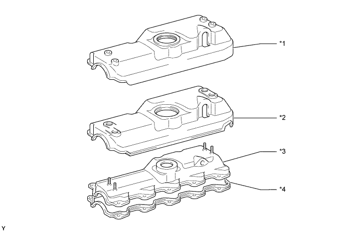
Text in Illustration *1 No. 2 Cylinder Head Cover *2 Sound-Insulation Cover *3 No. 1 Cylinder Head Cover *4 Cylinder Head Cover Gasket
-
-
Cylinder Head
-
The position of the valve in the fully closed state has been relocated closer to the piston to minimize the amount of air which is not used for combustion, thus improving the combustion efficiency.
-
The shape of the swirl chamber has been changed to one in which the offset has been eliminated in order to improve the combustion efficiency.
-
These improvements helped restrain the generation of CO, HC and black smoke.
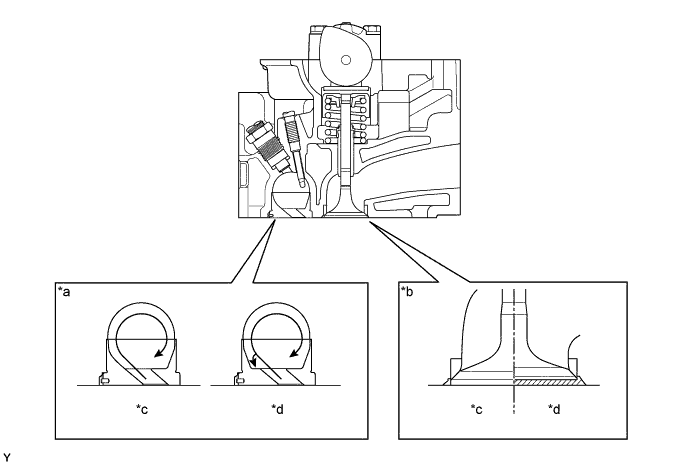
Text in Illustration *a Swirl Chamber *b Valve Position *c 5L Engine *d 3L Engine
-
-
Cylinder Head Gasket
-
A 4-layer steel laminate type cylinder head gasket, which excels in sealing performance and heat resistance, has been adopted.
-
Gaskets of different thicknesses are selected in accordance with the amount of protrusion of the pistons to reduce variations in the compression ratio.
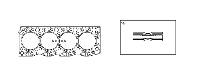
Text in Illustration *a A-A Cross Section - - -
There are 3 sizes of new cylinder head gaskets, marked "B", "D" or "F" according to piston protrusion. For details, refer to the Repair Manual.
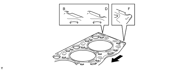
Text in Illustration 
Front - -
-
-
Cylinder Block
-
As with the 3L engine, a linerless cylinder block has been adopted.
-
The lay-out of the coolant passages between the bores has been revised to improve reliability.
-
The portion at the No. 3 crankshaft bearing journal has been reinforced to reduce noise and realize rigidity.
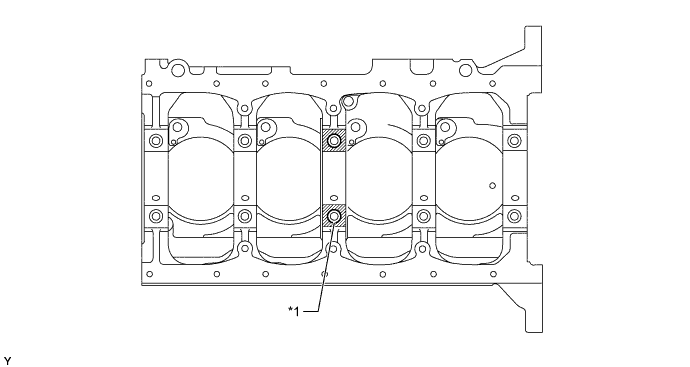
Text in Illustration *1 No. 3 Crankshaft Bearing Journal - -
-
-
Piston
-
The piston is made of aluminum alloy which excels in high-temperature strength. The skirt portion has been tin-plated to realize excellent wear resistance.
-
A cooling channel has been provided at the upper part of the piston to improve the piston's cooling performance.
-
To improve the wear resistance of the top ring groove, a FRM (Fiber Reinforced Metal) ring carrier has been adopted as on the 3L engine.
-
The surfaces of the No. 1 and No. 2 piston rings and of the oil ring have been gas-nitrided to improve their wear resistance.
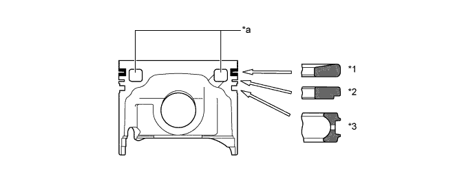
Text in Illustration *1 Compression Ring No. 1 *2 Compression Ring No. 2 *3 Oil Ring - - *a Cooling Channel - - 
FRM Ring Carrier 
Gas Nitrided Area
-
-
Connecting Rod
-
The connecting rod is made of high-strength steel to ensure the proper strength.
-
The small end of the connecting rod has been given a tapered shape to reduce weight.
-
Plastic region tightening bolts are used for the connecting rods.
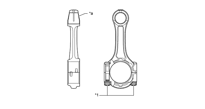
Text in Illustration *1 Plastic Region Tightening Bolt - - *a Tapered Shape - -
-
-
Crankshaft
-
The crankshaft has 5 journals and 8 balance weight.
-
The balance weights have been streamlined in order to reduce their friction loss by the engine oil during high rpm operation.
-
The fillet has been roll finished to improve rigidity.
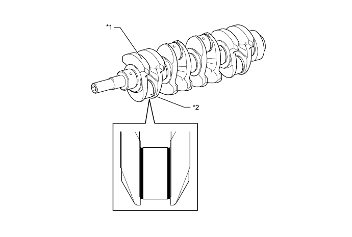
Text in Illustration *1 Balance Weight *2 Fillet Roll Finished - -
-
-
Valve Mechanism
-
As on the 3L engine, a direct drive OHC is used for valve drive mechanism.
-
Each cylinder has 1 intake valve and 1 exhaust valve.
Text in Illustration *1 Intake Valve *2 Exhaust Valve
-
-
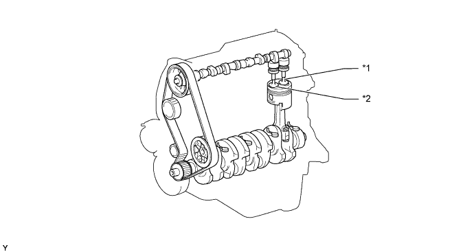
Camshaft
-
The cam nose has been chill treated to increase its abrasion resistance.

Text in Illustration *1 Cam Nose - -
-
-
Intake and Exhaust Valve and Valve Lifter
-
Heat-resistant steel is used for the intake and exhaust valves.
-
Unequal-pitch springs with anomalous cross section have been adopted to improve the surge resistance of the valve springs.
-
The adjusting shim has been located directly above the valve lifter. This construction allows the adjusting shim to be replaced without removing the camshaft, which improves the serviceability during valve clearance adjustment.
-
A cutout is provided in the valve lifter to improve the serviceability of replacing the adjusting shims.
Item Intake Valve Exhaust Valve Face Diameter 42.5 mm (1.67 in.) 36.0 mm (1.42 in.) Stem Diameter 8.0 mm (0.31 in.) ← 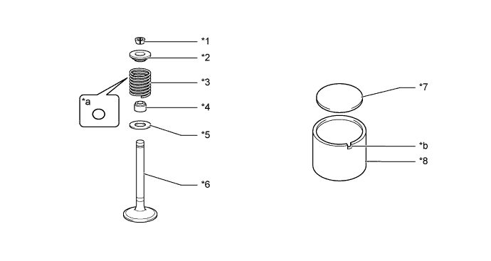
Text in Illustration *1 Keeper *2 Spring Retainer *3 Valve Spring *4 Oil Seal *5 Spring Seat *6 Valve *7 Adjusting Shim *8 Valve Lifter *a Cross-section *b Cutout
-
-