ENGINE UNIT DETAILS
-
CONSTRUCTION
-
Cylinder Head Cover
-
The cylinder head cover is made of aluminum to ensure rigidity.
-
A baffle plate is provided on the inside of the cylinder head cover to reduce the consumption of engine oil through blow-by gas.
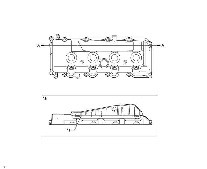
Text in Illustration *1 Baffle Plate - - *a A-A Cross Section - -
-
-
Cylinder Head
-
The cylinder head is made of aluminum alloy.
-
The injector has been located in the center of the combustion chamber in order to realize excellent engine performance and clean emission.
-
Two intake ports with different shapes have been combined to promote the mixture of fuel and air by optimizing the swirl in the cylinder.
-
A vertical 2-stage construction has been adopted for the water jacket to realize excellent cooling performance.
-
A glow plug is placed between the intake ports of each cylinder to ensure startability.
-
The passage for the EGR is provided in the cylinder head. By cooling the exhaust gas, this makes it possible to re-circulate the great amount of exhaust gas.
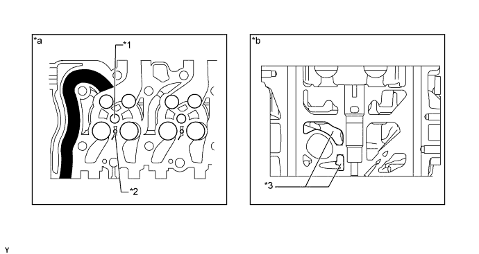
Text in Illustration *1 Injector Hole *2 Glow Plug Hole *3 Water Jacket - - *a View of Back Side *b Cylinder Head Cross Section 
EGR Passage - -
-
-
Cylinder Head Gasket
-
A steel-laminate type cylinder head gasket has been adopted.
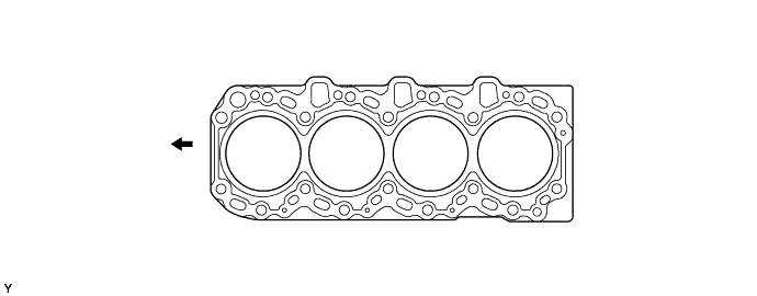
Text in Illustration 
Front - - -
There are 5 sizes of new cylinder head gaskets, marked "A", "B", "C", "D" or "E" according to piston protrusion. For details, refer to the Repair Manual.
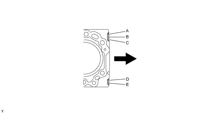
Text in Illustration Rear - -
-
-
Cylinder Block
-
This cylinder block is constructed of linerless cast iron alloy.
-
A rib has been added to the back of the cylinder block to reduce engine vibration.
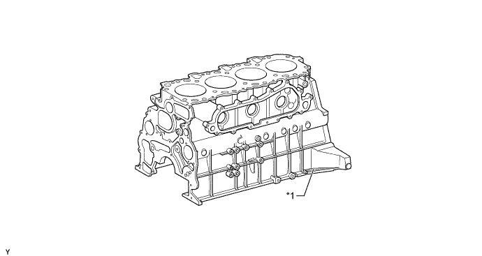
Text in Illustration *1 Rid - -
-
-
Piston
-
In conjunction with the adoption of direct injection, piston provided with combustion chamber has been adopted.
-
The piston is made of aluminum alloy.
-
A cooling channel has been provided to reduce the piston temperature.
-
To improve the wear resistance of the top ring groove, a Ni-resist cast iron ring carrier has been adopted.
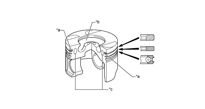
Text in Illustration *a Ni-Resist Cast Iron Ring Carrier *b Combustion Chamber *c Cooling Channel - -
-
-
Connecting Rod
-
The connecting rods are made of high-strength material to ensure the proper strength.
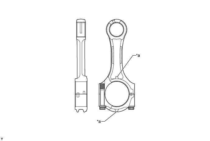
Text in Illustration *a Front Mark - -
-
-
Crankshaft
-
The crankshaft has 5 journals and 8 balance weight.
-
The crankshaft is made of a highly-strengthened material without lead.
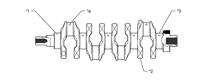
Text in Illustration *1 No. 1 Journal *2 Balance Weight *3 No. 5 Journal - - *a Oil Hole - -
-
-
Connecting Rod Bearing and Crankshaft Bearing
-
As on the 1KD-FTV engine, the microgroove bearings that have fine grooves on the bearing surface have been adopted to improve the conformance with the shaft and the retention of engine oil.
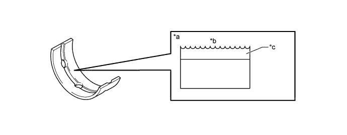
Text in Illustration *a Bearing Surface *b Micro Groove *c Aluminum Alloy Lining - -
-
-
Valve Mechanism
-
The valves are directly opened and closed by 2 camshafts.
-
The intake camshaft is driven by a timing belt, while the exhaust camshaft is driven through gear on the intake camshaft.
-
Small-diameter and flat-teeth gears are used for driving the exhaust camshaft in order to reduce gear noise.
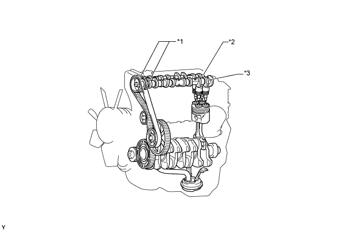
Text in Illustration *1 Gear *2 Exhaust Camshaft *3 Intake Camshaft - -
-
-
Camshaft
-
The cam nose has been chill treated to increase its abrasion resistance.
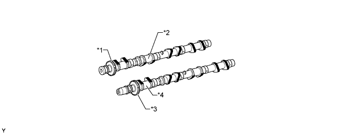
Text in Illustration *1 Camshaft Driven Gear *2 Exhaust Camshaft *3 Camshaft Drive Gear *4 Intake Camshaft Chill Treated - -
-
-
Intake and Exhaust Valves
-
The adjusting shim has been located directly above the valve lifter. This construction allows the adjusting shim to be replaced without removing the camshaft, which improves the serviceability during valve clearance adjustment.
-
A cutoff is provided in the valve lifter to realize good serviceability of the replacing the adjusting shims.
Tech Tips
Adjusting shims are available in 32 sizes in increments of 0.025 mm (0.0020 in.), from 2.525 mm (0.0994 in.) to 3.30 mm (0.1299 in.). For details, refer to the Repair Manual.
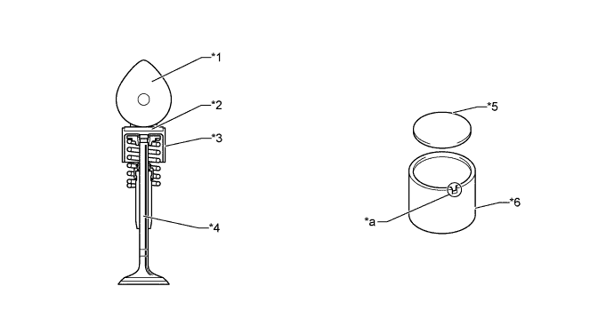
Text in Illustration *1 Camshaft *2 Adjusting Shim *3 Valve Lifter *4 Valve *5 Adjusting Shim *6 Valve Lifter *a Cutout - -
-
-
Timing Train
-
The supply pump, vacuum pump, and oil pump are driven by the camshaft timing gear.
-
The idler gear is constructed with a scissors gear on its front and back to reduce noise.
-
The automatic tensioner suppresses noise generated by the timing belt.
-
The maintenance interval of the timing belt is every 150000 km.
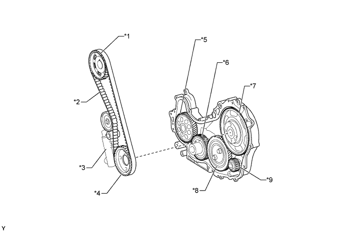
Text in Illustration *1 Camshaft Timing Pulley No. 2 *2 Timing Belt *3 Automatic Tensioner *4 Camshaft Timing Pulley No. 1 *5 Oil Pump Drive Gear *6 Crankshaft Timing Gear *7 Supply Pump Drive Gear *8 Idle Gear *9 Vacuum Pump Drive Gear - -
-
-
Serpentine Belt Drive System
-
Accessory components are driven by a serpentine belt consisting of a single V-ribbed belt. It reduces the overall engine length, weight and number of engine parts.
-
An automatic tensioner eliminates the need for tension adjustment.
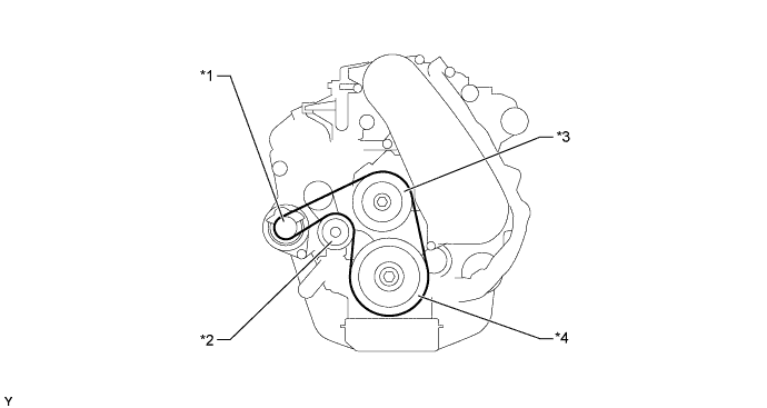
Text in Illustration *1 Alternator Pulley *2 Idler Pulley *3 Water Pump Pulley *4 Crankshaft Pulley -
To inspect the drive belt check that the indicator mark is positioned in the indicator range. If not, replace the drive belt.
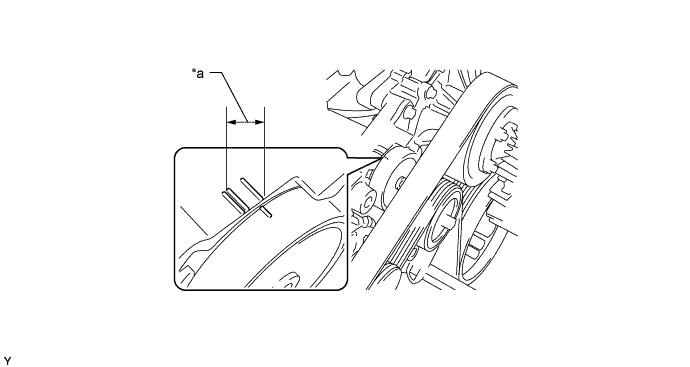
Text in Illustration *a Indicator Range - -
-
-