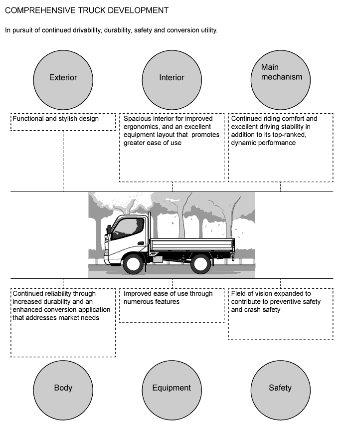
FEATURES PERFORMANCE
-
OUTLINE
-
Concept
-
1KD-FTV Engine
-
The 1KD-FTV TOYOTA D-4D (Direct Injection, 4-stroke Common-rail Diesel Engine) is a 3.0-liter, inline 4-cylinder, 16-valve DOHC with intercooler turbocharged diesel engine.
Item Specification No. of Cyls. and Arrangement 4-Cylinder, In-line Valve Mechanism 16 Valve, DOHC, Belt and Gear Drive Displacement 2982 cm3(182.0 cu.in.)
Bore x Stroke 96.0 mm x 103.0 mm (3.78 in. x 4.06 in.) Max. Output (EEC) 106 kW @ 3400 rpm Max. Torque (EEC) 300 N*m @ 1200-3200 rpm 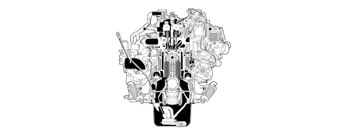
-
-
5L Engine
-
The engine has been changed from the 3L engine (2.8L) that was used on the previous Dyna 100/150 to the 5L engine (3.0L) that provides more torque through increased cylinder displacement.
-
Based on the 3L engine, the 5L engine offers greater torque, better fuel economy, and lower exhaust emissions by improving combustion. Efficiency and tuning the fuel injection timing to an optimal level.
Item Specification No. of Cyls. and Arrangement 4-Cylinder, In-line Valve Mechanism 8-Valve, OHC, Belt Drive Displacement 2986 cm3(182.2 cu. in.)
Bore x Stroke 99.5 mm x 96.0 mm (3.92 in. x 3.78 in.) Max. Output (EEC) 66 kW @ 4000 rpm Max. Torque (EEC) 192 N*m @ 2400 rpm 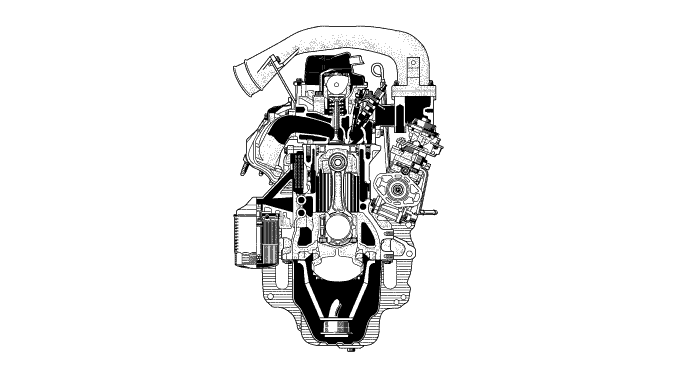
-
-
G54 Manual Transmission
-
A G54 5-speed manual transmission is used on the Dyna 100 except for Singapore package.
Item Specification Gear Ratio 1st 4.452 2nd 2.398 3rd 1.414 4th 1.000 5th 0.802 Reverse 4.472
-
-
R451 Manual Transmission
-
A R451 5-speed manual transmission is used on Singapore package models.
Item Specification Gear Ratio 1st 4.313 2nd 2.330 3rd 1.436 4th 1.000 5th 0.838 Reverse 4.220
-
-
R452 Manual Transmission
-
A R452 5-speed manual transmission is used on the Dyna 150 except for Singapore package.
Item Specification Gear Ratio 1st 5.146 2nd 2.780 3rd 1.509 4th 1.000 5th 0.830 Reverse 5.035
-
-
Suspension
-
An independent front suspension or a leaf spring rigid front suspension has been provided depending on the specifications.
-
A leaf spring rigid rear suspension has been used on all models.
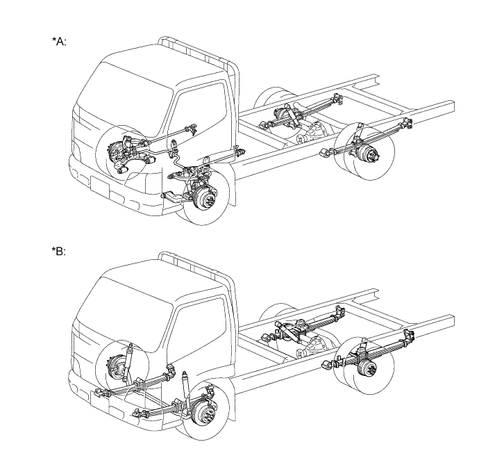
Text in Illustration *A Models with an Independent Front Suspension *B Models with a Leaf Spring Rigid Front Suspension
-
-
Steering Wheel Assembly
-
A 2-spoke steering wheel assembly is used to improve the visibility of the combination meter assembly.
-
The steering wheel assembly made of urethane or polypropylene has been provided depending on the specifications.
-
The steering wheel pad (horn button assembly) with an EA (Energy Absorbing) feature has been used.
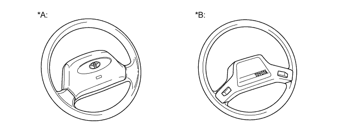
Text in Illustration *A Models with the Steering Wheel Assembly Made of Urethane *B Models with the Steering Wheel Assembly Made of Polypropylene -
The installation angle of the steering wheel assembly has been changed to achieve an optimal driving position thus improving drivability and comfort.
Text in Illustration *a New Models *b Previous Models
-
-
Steering Column
-
The fixed type steering column or the tilt-and-telescopic steering column has been provided depending on the specifications.
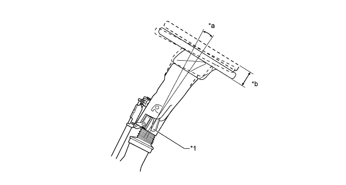
Text in Illustration *1 Tilt-and Telescopic Lever - - *a 8.2°Compared to Previous (+1.8°) *b 35 mm Compared to Previous (+5 mm)
-
-
Brake
-
Ventilated disc brakes have been used for the front and drum brakes for the rear on all models.
-
An in-wheel parking brake or a center parking brake has been provided depending on the specifications.
-
A floor type parking brake lever assembly has been incorporated for improved ease of use.
-
-
Cab
-
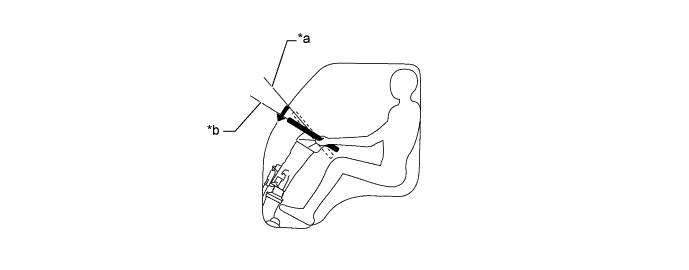
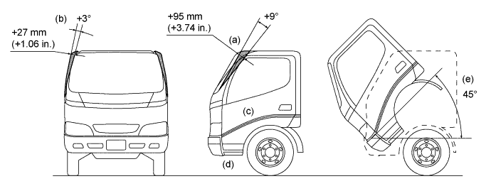
Ample cabin space has been achieved by increasing front head clearance (a) and the front pillar angle (b), thus achieving improved ergonomics.
-
(c) The opening angle of the door hinges and the opening area of the door have been increased to make it easier to get in and out.
-
(e) For part of the single-cabin models is provided with a tilt mechanism to ensure access for servicing the vehicle.
-
(d) The stepping area of the front step has been increased to make it easier to get in and out.
-
-
Deck
-
A steel deck comes on all complete models.
-
The header board has been kept from protruding out into the bed area, allowing it to lay flat, resulting in improved use of the bed.
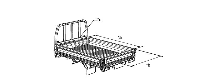
Text in Illustration *a
-
Short: 2850 mm (112.2 in.)
-
Long: 3110 mm (122.4 in.)
*b 1600 mm (63.0 in.) *c The header board has been kept from protruding out into the bed area, allowing it to lay flat, resulting in improved use of the bed. - - -
-
-
Frame
-
The frames have been designed exclusively for the IFS (Independent Front Suspension) models and the RFS (Rigid Front Suspension) models.
Destination Front Suspension Type Deck Type Wheel Base General Countries Except Singapore Rigid Steel High Deck Short (2300 mm) Long (2545 mm) Singapore Independent Steel Flat Deck (Just Low) Short (2300 mm) Long (2545 mm) Component Outline No. 2 Frame Crossmember Sub-assembly*1 Shaped to facilitate the installation of various types of wiring harnesses and pipes. No. 2 Frame Crossmember Sub-assembly*2 Located near the No. 1 spring bracket, No. 2 frame crossmember sub-assembly is riveted to the top and bottom surfaces of the front frame side rail in order to ensure the rigidity of the area where the suspension is mounted. No. 3 Frame Crossmember Sub-assembly The wall of the No. 3 frame crossmember sub-assembly has been made thicker to ensure its strength and rigidity for mounting the torsion bar anchor arm and the rear engine mount. No. 5 Frame Crossmember Sub-assembly No. 5 frame crossmember sub-assembly is made of a pipe material that has been butted for weight reduction by decreasing the thickness of the pipe-wall in its midsection. No. 4 Frame Crossmember Sub-assembly It has a C-shape to improve the suspension performance of the brackets. Side Rail*1 It has a welded neck section until just before the No. 3 frame crossmember sub-assembly to ensure a highly rigid construction. Side Rail*2 It has been newly designed exclusively for the RFS frame to ensure a lightweight and highly rigid construction. Front Suspension Member Assembly In order to ensure a lightweight and highly rigid construction, support pipes have been attached to run between the mid-sections of the front and rear suspension members, resulting in the following shape: II. Front Frame Crossmember Sub-assembly*1 It has a C-shape cross-section to ensure a lightweight and highly rigid construction. Front Frame Crossmember Sub-assembly*2 Located at the front tip of the frame, front frame crossmember sub-assembly is riveted to the top and bottom surfaces of the side rails to ensure a high level of rigidity. Tech Tips
*1: for IFS models
*2: for RFS models
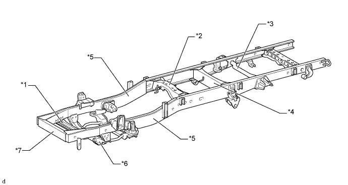
Text in Illustration (Frame for IFS: ) *1 No. 2 Frame Crossmember Sub-assembly *2 No. 3 Frame Crossmember Sub-assembly *3 No. 5 Frame Crossmember Sub-assembly *4 No. 4 Frame Crossmember Sub-assembly *5 Side Rail *6 Front Suspension Member Assembly *7 Front Frame Crossmember Sub-assembly - - 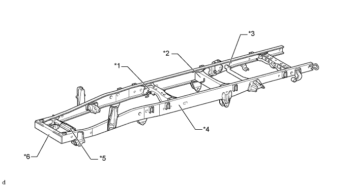
Text in Illustration (Frame for RFS: ) *1 No. 3 Frame Crossmember Sub-assembly *2 No. 4 Frame Crossmember Sub-assembly *3 No. 5 Frame Crossmember Sub-assembly *4 Side Rail *5 No. 2 Frame Crossmember Sub-assembly *6 Front Frame Crossmember Sub-assembly
-
-
Improved Visibility
-
Front and side visibility have been improved by increasing the area of the windshield glass and by optimizing the driving position.
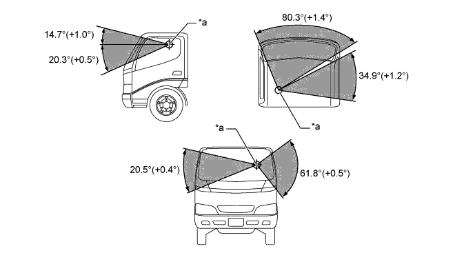
Text in Illustration *a Eye-point - -
-
-
High-strength Cab
-
A high-strength cab construction which help dampen the impact in the case of a collision has been achieved by adopting the effective floor side members.
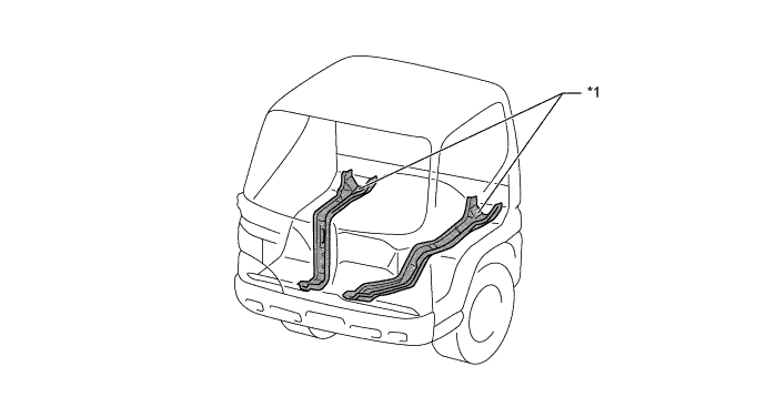
Text in Illustration *1 Floor Side Member - -
-
-
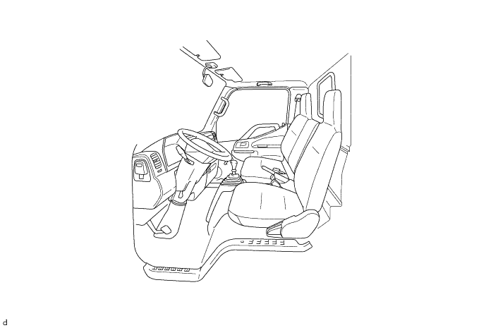
Front Cab Interior Design
-
The spacious cabin interior and the enlarged windshield create a bright and functional interior space.
-
The instrument panel sub-assembly is designed to extend from the shoulder of the door to achieve an open feeling.
-
The top of the instrument panel sub-assembly is kept low to improve visibility.
-
-