WHEN REMOVING,INSTALLING,REPAIRING OR REPLACING PARTS WHEEL ALIGNMENT STANDARD
The necessary procedures (adjustment, calibration, initialization, or registration) that must be performed after completing the front wheel alignment procedure are shown below.
| Necessary Procedure After Parts Removed/Installed/Replaced | ||||||||||||||||
|---|---|---|---|---|---|---|---|---|---|---|---|---|---|---|---|---|
|
Note
-
When the brake pedal is first depressed after replacing the brake pads or pushing back the disc brake piston, DTC C1341, C1342, C1343 and/or C1344 may be stored. As there is no malfunction, clear the DTCs.
-
While the auxiliary battery is connected, even if the power switch is off, the brake control system activates when the brake pedal is depressed or any door courtesy switch is turned on. Therefore, when servicing, do not depress the brake pedal or open/close the doors while the auxiliary battery is connected.
-
MEASURE VEHICLE HEIGHT (for 2WD)
Note
-
Before inspecting the wheel alignment, adjust the vehicle height to the specified value.
-
Be sure to perform measurement on a level surface.
-
If it is necessary to go under the vehicle for measurement, confirm that the parking brake is applied and the vehicle is secured with chocks.
-
Inspect while the vehicle is unloaded.
-
The standard value shown here is a value that is used for performing a wheel alignment and does not indicate the height of an actual vehicle.
-
Bounce the vehicle up and down at the corners to stabilize the suspension.
-
Measure the vehicle height.
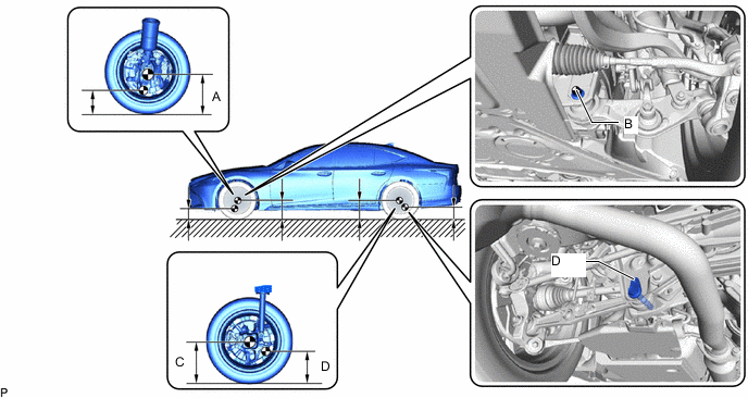
-
A: Ground clearance of front wheel center
Measurement Points:
-
B: Ground clearance of front center position of front No. 2 suspension lower arm assembly front bush installation bolt
-
C: Ground clearance of rear wheel center
-
D: Ground clearance of pin hole center of the rear suspension arm attachment sub-assembly
-
-
-
INSPECT CAMBER, CASTER AND STEERING AXIS INCLINATION (FRONT WHEEL ALIGNMENT, for 2WD)
Note
Inspect while the vehicle is unloaded.
-
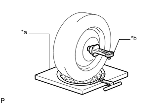
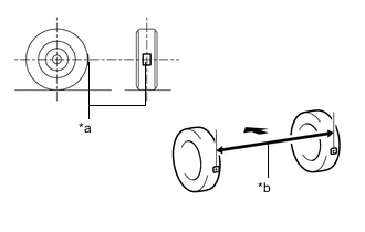
*a Turning Radius Gauge *b Camber-caster-kingpin Gauge Install a camber-caster-kingpin gauge and place the front wheels on the center of a turning radius gauge.
-
Inspect the camber, caster and steering axis inclination.
-
-
INSPECT TOE-IN (FRONT WHEEL ALIGNMENT, for 2WD)
Note
Inspect while the vehicle is unloaded.
-
Bounce the vehicle up and down at the corners to stabilize the suspension.
-
Release the parking brake and move the shift lever to N.
-
Push the vehicle straight ahead approximately 5 m (16.4 ft.). (Step C)
-

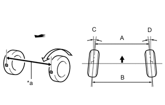
*a Tread Center Mark *b Dimension B 
Front of the Vehicle Put tread center marks on the rearmost points of the front wheels and measure the distance between the marks (dimension B).
-
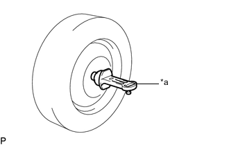
Slowly push the vehicle straight ahead to cause the front wheels to rotate 180°. Use the front tire valve as a reference point.
Tech Tips
Do not allow the wheels to rotate more than 180°. If the wheels rotate more than 180°, perform the procedure from step C again.
-

*a Dimension A Front of the Vehicle Measure the distance between the tread center marks on the front of the wheels (dimension A).
Tech Tips
Measure "B - A" only when "C + D" cannot be measured.
If the toe-in is not within the specified range, adjust it at the steering rack ends.
-
-
INSPECT WHEEL ANGLE (FRONT WHEEL ALIGNMENT, for 2WD)
-
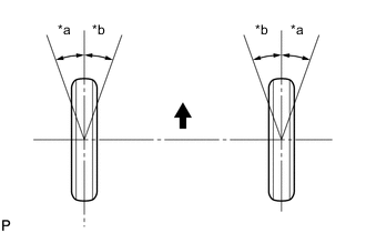
*a Inside *b Outside Front of the Vehicle Put tread center marks on the rearmost points of a turning radius gauge.
-
Turn the steering wheel fully to the left and right and measure the turning angle.
Note
Inspect while the vehicle is unloaded.
-
If the right and left inside wheel angles differ from the specified value, check and adjust the right and left steering rack end lengths.
-
-
-
MEASURE VEHICLE HEIGHT (for AWD)
Note
-
Before inspecting the wheel alignment, adjust the vehicle height to the specified value.
-
Be sure to perform measurement on a level surface.
-
If it is necessary to go under the vehicle for measurement, confirm that the parking brake is applied and the vehicle is secured with chocks.
-
Inspect while the vehicle is unloaded.
-
The standard value shown here is a value that is used for performing a wheel alignment and does not indicate the height of an actual vehicle.
-
Bounce the vehicle up and down at the corners to stabilize the suspension.
-
Measure the vehicle height.
-
A: Ground clearance of front wheel center
Measurement Points:
-
B: Ground clearance of front center position of front No. 2 suspension lower arm assembly front bush installation bolt
-
C: Ground clearance of rear wheel center
-
D: Ground clearance of pin hole center of the rear suspension arm attachment sub-assembly
-
-
-
INSPECT CAMBER, CASTER AND STEERING AXIS INCLINATION (FRONT WHEEL ALIGNMENT, for AWD)
Note
Inspect while the vehicle is unloaded.
-
*a Turning Radius Gauge *b Camber-caster-kingpin Gauge Install a camber-caster-kingpin gauge and place the front wheels on the center of a turning radius gauge.
-
Inspect the camber, caster and steering axis inclination.
-
-
INSPECT TOE-IN (FRONT WHEEL ALIGNMENT, for AWD)
Note
Inspect while the vehicle is unloaded.
-
Bounce the vehicle up and down at the corners to stabilize the suspension.
-
Release the parking brake and move the shift lever to N.
-
Push the vehicle straight ahead approximately 5 m (16.4 ft.). (Step C)
-
*a Tread Center Mark *b Dimension B Front of the Vehicle Put tread center marks on the rearmost points of the front wheels and measure the distance between the marks (dimension B).
-
Slowly push the vehicle straight ahead to cause the front wheels to rotate 180°. Use the front tire valve as a reference point.
Tech Tips
Do not allow the wheels to rotate more than 180°. If the wheels rotate more than 180°, perform the procedure from step C again.
-
*a Dimension A Front of the Vehicle Measure the distance between the tread center marks on the front of the wheels (dimension A).
Tech Tips
Measure "B - A" only when "C + D" cannot be measured.
If the toe-in is not within the specified range, adjust it at the steering rack ends.
-
-
INSPECT WHEEL ANGLE (FRONT WHEEL ALIGNMENT, for AWD)
-
*a Inside *b Outside Front of the Vehicle Put tread center marks on the rearmost points of a turning radius gauge.
-
Turn the steering wheel fully to the left and right and measure the turning angle.
Note
Inspect while the vehicle is unloaded.
-
If the right and left inside wheel angles differ from the specified value, check and adjust the right and left steering rack end lengths.
-
-
-
INSPECT CAMBER (REAR WHEEL ALIGNMENT)
Note
Inspect while the vehicle is unloaded.
-
*a Camber-caster-kingpin Gauge Install a camber-caster-kingpin gauge.
-
w/ Air suspension:
Inspect the camber.
Tech Tips
Camber is not adjustable. If the measurement is not within the specified range, inspect the suspension parts for damage and/or wear, and replace them if necessary.
-
w/o Air suspension:
Inspect the camber.
Tech Tips
Camber is not adjustable. If the measurement is not within the specified range, inspect the suspension parts for damage and/or wear, and replace them if necessary.
-
-
INSPECT TOE-IN (REAR WHEEL ALIGNMENT)
Note
Inspect while the vehicle is unloaded.
-
Bounce the vehicle up and down at the corners to stabilize the suspension.
-
Release the parking brake and move the shift lever to N.
-
Push the vehicle straight ahead approximately 5.0 m (16.4 ft.). (Step A)
-
*a Tread Center Mark *b Dimension B Front of the Vehicle Put tread center marks on the rearmost points of the rear wheels and measure the distance between the marks (dimension B).
-
Slowly push the vehicle straight ahead to cause the rear wheels to rotate 180°. Use the rear tire valve as a reference point.
Tech Tips
Do not allow the wheels to rotate more than 180°. If the wheels rotate more than 180°, perform the procedure from step A again.
-
*a Dimension A Front of the Vehicle Measure the distance between the tread center marks on the front of the rear wheels (dimension A).
Tech Tips
Measure "B - A" only when "C + D" cannot be measured.
If the toe-in is not within the specified range, adjust it at the toe control link sub-assembly.
-