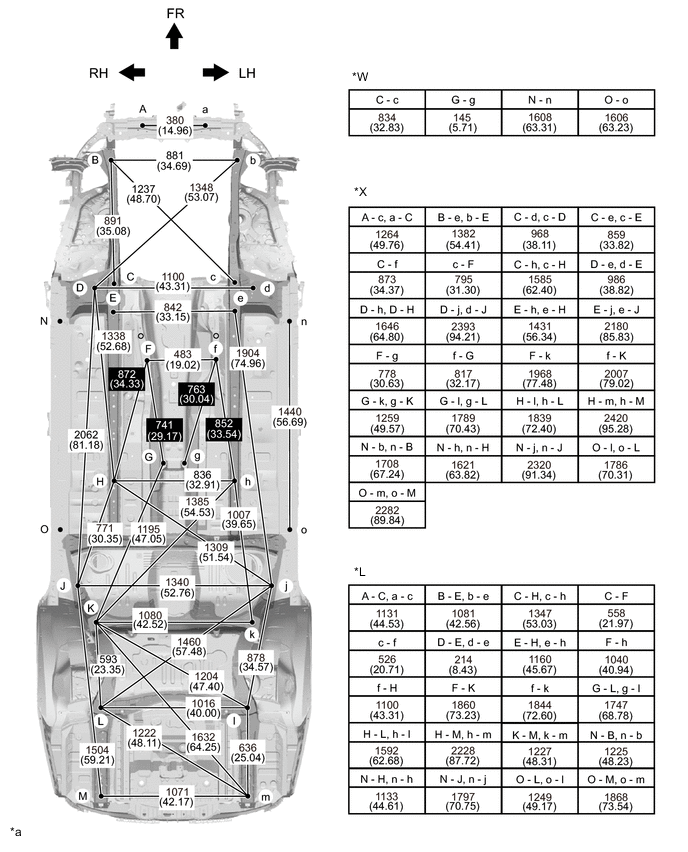
UNDER BODY(for AWD) POINT-TO-POINT DISTANCE
Tech Tips
-
Point F, f on the vehicle are asymmetrical.
-
In cases in which only one dimension is given, left and right are symmetrical.
-
For symbols, capital letters indicate right side of vehicle, small letters indicate left side of vehicle (seen from rear).
-
Set point N, n as the position 150 mm (5.91 in.) towards the rear of the vehicle from the lower surface of the rocker panel at the center of the front jack up point bracket installation hole.
-
Set point O, o as the position 150 mm (5.91 in.) towards the front of the vehicle from the lower surface of the rocker panel at the center of the rear jack up point bracket installation hole.
| Symbol | Name | Hole Diameter mm (in.) |
|---|---|---|
| A, a | Front Cross Member Lower Standard Hole | φ18 (0.71) |
| B, b | Front Suspension Crossmember Installation Nut | M16 (0.63) |
| C, c | Front Suspension Crossmember Installation Nut | M16 (0.63) |
| D, d | Torque Box Standard Hole | φ25 (0.98) |
| E, e | Front Side Member Reinforcement No.5 Standard Hole | φ10 (0.39) |
| F, f | Engine Rear Support Member Installation Nut | M10 (0.39) |
| G, g | Propeller Shaft Center Bearing Support Installation Nut | M10 (0.39) |
| H, h | Front Floor Under Reinforcement Standard Hole | φ15 (0.59) |
| J, j | Rear Floor Side Member Standard Hole | φ18 (0.71) |
| K, k | Rear Suspension Crossmember Installation Nut | M14 (0.55) |
| L, l | Rear Suspension Crossmember Installation Nut | M14 (0.55) |
| M, m | Muffler Support Installation Nut | M8 (0.31) |
| N, n | Under Surface of the Rocker Panel | - |
| O, o | Under Surface of the Rocker Panel | - |
 |
Symmetric distance |  |
Asymmetric distance |
| *a | mm (in.) |
- | - |
| *W | Width distance | *X | Diagonal distance |
| *L | Length distance | - | - |