FIT STANDARD / ADJUSTMENT METHOD ADJUSTMENT
-
INSPECT FITTING OF HOOD SUB-ASSEMBLY
-
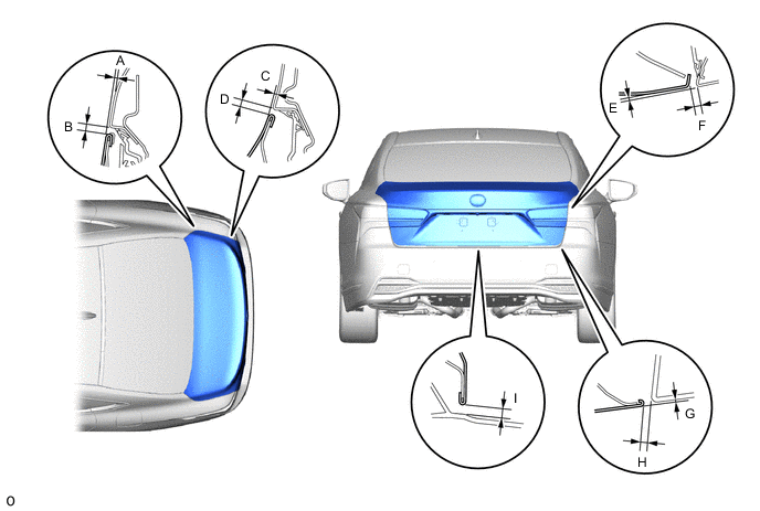
Check that the all fitting dimensions are within the reference value ranges.
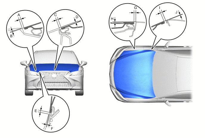
Tech Tips
-
Centering bolts are used to mount the hood hinge to the vehicle body and hood. The hood cannot be adjusted with the centering bolts on. Substitute the centering bolts for standard bolts when making adjustments.
-
Use the same procedure for RHD and LHD vehicles.
-
The procedure listed below is for LHD vehicles.
-
-
ADJUST HOOD SUB-ASSEMBLY
-
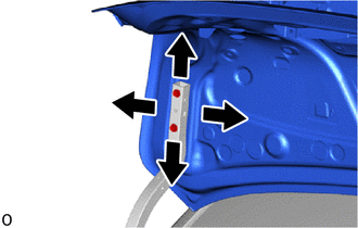
Adjustment in longitudinal direction of hood and horizontal direction of hood rear end.
-
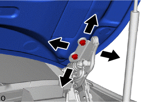
Loosen the hood hinge assembly bolts and adjust.
- Torque:
- 13 N*m { 133 kgf*cm, 10 ft.*lbf }
Note
Replace the bolts with the supplied bolts before performing adjustment, as centering bolts are used.
-
-
Adjustment in vertical direction of hood front left and right ends.
-
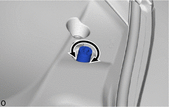
Turn the cushion to adjust.
-
-
Remove the front bumper cover.
-
except Sport Package
-
for Sport Package
-
-
Remove the hood lock release lever protector.
-
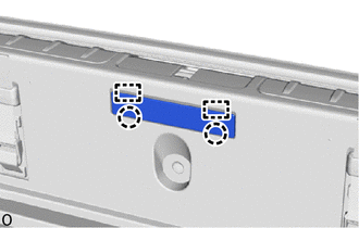
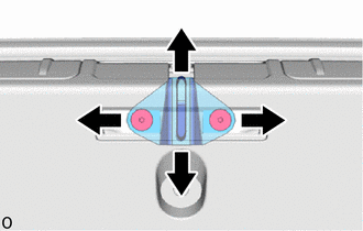
Adjustment in vertical and horizontal directions of hood front end.
-
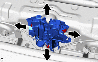
Loosen the 3 bolts and adjust.
- Torque:
- 8.0 N*m { 82 kgf*cm, 71 in.*lbf }
Note
Replace the bolts with the supplied bolts before performing adjustment, as centering bolts are used.
-
-
Install the hood lock release lever protector.
-
Install the front bumper cover.
-
except Sport Package
-
for Sport Package
-
-
-
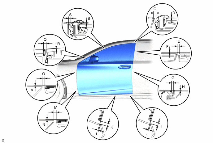
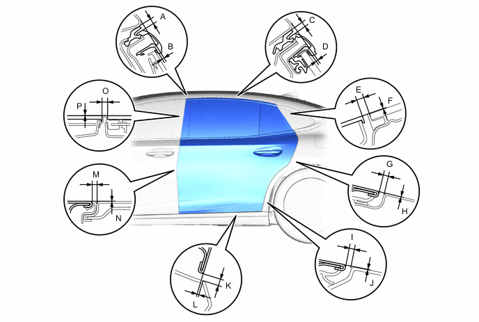
INSPECT FRONT DOOR PANEL SUB-ASSEMBLY LH
-
Check that the clearance measurements of areas A to R are within the standard ranges.
Tech Tips
-
Centering bolts are used to mount the door hinge to the vehicle body and door. The door cannot be adjusted with the centering bolts on. Substitute the centering bolts for standard bolts when making adjustments.
-
Use the same procedure for the RH and LH sides.
-
The procedure listed below is for the LH side.
-
-
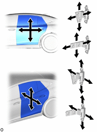
ADJUST FRONT DOOR PANEL SUB-ASSEMBLY LH
-
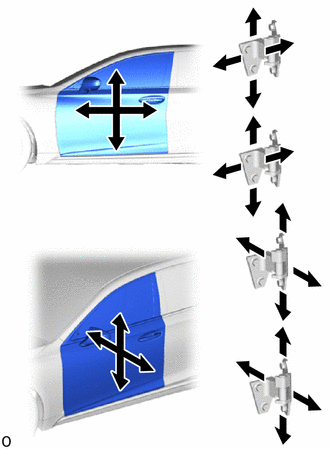
Using SST, loosen the hinge bolts on the body and adjust the door position.
- SST
- 09812-00010
-
Tighten the hinge bolts on the body after the adjustment.
- Torque:
- 26 N*m { 265 kgf*cm, 19 ft.*lbf }
-
Loosen the hinge bolts on the door and adjust the door position.
-
Tighten the hinge bolts on the door after the adjustment.
- Torque:
- 21 N*m { 214 kgf*cm, 15 ft.*lbf }
-
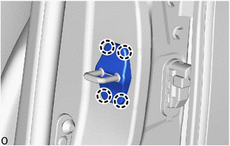
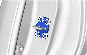
Detach the claw and remove the door lock striker cover.
-
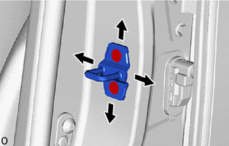
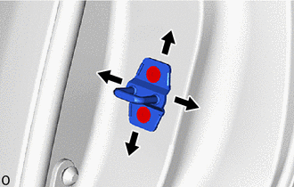
Using a T40 "TORX" socket wrench, adjust the striker position by slightly loosening the striker mounting screws and hitting the striker with a plastic-faced hammer.
-
Using a T40 "TORX" socket wrench, tighten the striker mounting screws after the adjustment.
- Torque:
- 23 N*m { 235 kgf*cm, 17 ft.*lbf }
-
Attach the claw to install the door lock striker cover.
-
-
INSPECT REAR DOOR PANEL SUB-ASSEMBLY LH
-
Check that the clearance measurements of areas A to R are within the standard ranges.
Tech Tips
-
Centering bolts are used to mount the door hinge to the vehicle body and door. The door cannot be adjusted with the centering bolts on. Substitute the centering bolts for standard bolts when making adjustments.
-
Use the same procedure for the RH and LH sides.
-
The procedure listed below is for the LH side.
-
-
ADJUST REAR DOOR PANEL SUB-ASSEMBLY LH
-
Using SST, loosen the hinge bolts on the body and adjust the door position.
- SST
- 09812-00010
-
Tighten the hinge bolts on the body after the adjustment.
- Torque:
- 26 N*m { 265 kgf*cm, 19 ft.*lbf }
-
Loosen the hinge bolts on the door and adjust the door position.
-
Tighten the hinge bolts on the door after the adjustment.
- Torque:
- 21 N*m { 214 kgf*cm, 15 ft.*lbf }
-
Detach the claw and remove the door lock striker cover.
-
Using a T40 "TORX" socket wrench, adjust the striker position by slightly loosening the striker mounting screws and hitting the striker with a plastic-faced hammer.
-
Using a T40 "TORX" socket wrench, tighten the striker mounting screws after the adjustment.
- Torque:
- 23 N*m { 235 kgf*cm, 17 ft.*lbf }
-
-
INSPECT LUGGAGE COMPARTMENT DOOR PANEL ASSEMBLY
-
Check that the clearance measurements of areas A to I are within the standard ranges.
Tech Tips
Centering bolts are used to mount the door hinge to the vehicle body and door. The door cannot be adjusted with the centering bolts on. Substitute the centering bolts for standard bolts when making adjustments.
-
-
ADJUST LUGGAGE COMPARTMENT DOOR PANEL ASSEMBLY
-
Remove the luggage compartment door hinge cover LH.
Tech Tips
Use the same procedure for the RH and LH sides.
-
Loosen the 4 hinge bolts on the body and adjust the door position.
-
Tighten the 4 hinge bolts on the body after the adjustment.
- Torque:
- 8.0 N*m { 82 kgf*cm, 71 in.*lbf }
-
Detach the claw and guide and remove the rear luggage room cover.
-
Using a T40 "TORX" socket, adjust the striker position by slightly loosening the striker mounting screws and hitting the striker with a plastic hammer.
-
Using a T40 "TORX" socket, tighten the striker mounting screws after the adjustment.
- Torque:
- 23 N*m { 235 kgf*cm, 17 ft.*lbf }
-
Attach the claw and guide to install the rear luggage room cover.
-