ROOF PANEL ASSEMBLY REPLACEMENT
-
LASER BRAZED ROOF PANEL REPLACEMENT USING ADHESIVE
Symbol Meaning 
Remove Weld Points 
Plug Weld 
Fillet Weld 
Body Sealer
-
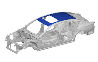
The laser brazed roof panel is repaired using a roof panel reinforcement, roof panel reinforcement No.1 and adhesive.
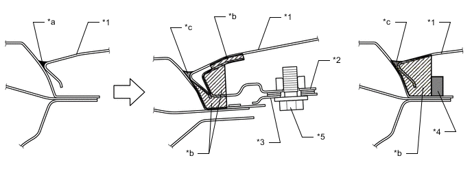
*1 ROOF PANEL *2 ROOF PANEL REINFORCEMENT *3 ROOF PANEL REINFORCEMENT NO.1 *4 ROOF DRIP MOULDING SUB-ASSEMBLY *5 BOLT - - *a Laser Brazing *b Adhesive *c Adhesive and Sealer - - -
Roof panel rough cutting.
Note
Carefully cut the roof panel so not to damage the internal reinforcement.
-
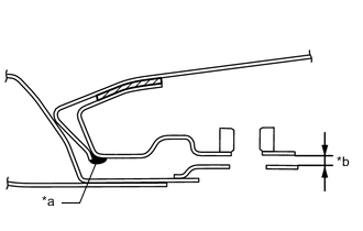
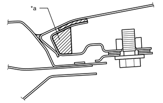
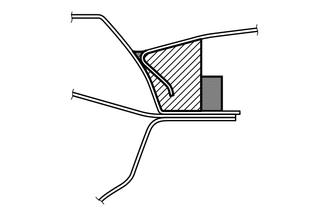
Sand the roof panel and brazing filler metal left on the vehicle using a belt grinder to make them smooth.
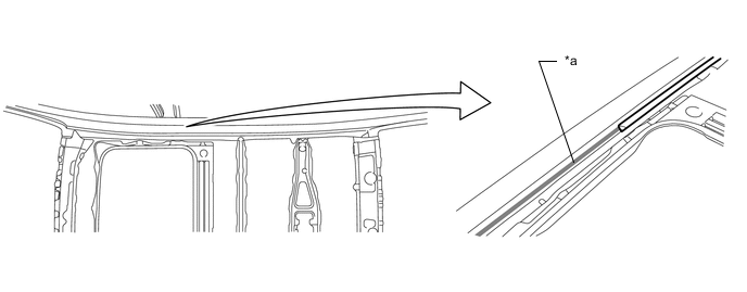
*a brazing filler metal part - - Tech Tips
-
Do not damage the area above *a (brazing filler metal part) of the roof side outer upper No.1 rail.
-
All of the brazing filler metal does not need to be sanded.
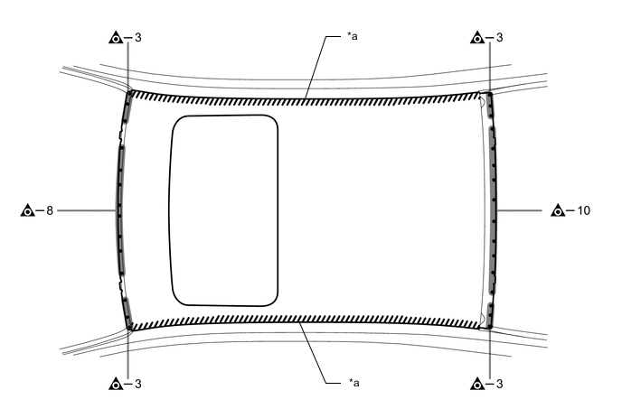
*a Laser Brazing - - 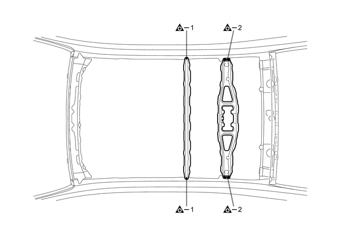
-
-
Roof panel reinforcement installation.
-
Remove the paint film where the adhesive will be applied for the roof panel and roof panel reinforcement.
Tech Tips
On the roof panel side, remove the paint film from the roof panel reinforcement installation area only.
-
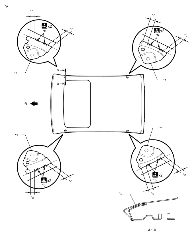
Place marks to indicate the roof panel reinforcement installation position.
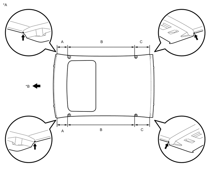
*A Lower Face *B Front Tech Tips
Perform the measurement along the roof panel surface.
Standard value Area Measurement Area Measurement A 203 mm (7.99 in.) B 1211 mm (47.68 in.) C 276 mm (10.87 in.) - - -
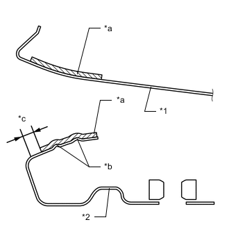
*1 ROOF PANEL *2 ROOF PANEL REINFORCEMENT *a Adhesive *b Protrusions *c 3 mm (0.12 in.) Apply adhesive in the positions shown in the illustration and place the roof panel reinforcement at the marked positions on the roof panel.
Tech Tips
-
Perform the procedures one area at a time.
-
Apply enough adhesive so that *b is covered.
-
-
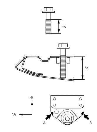
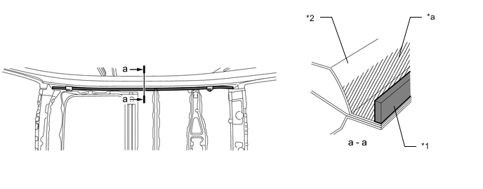
*A Front *B RH *b 20 mm (0.79 in.) Adjust the clearance of *a using an adjustmentbolt to the value shown below.
No.1 No.2 A 13.2 mm (0.52 in.) 9.0 mm (0.35 in.) B 13.1 mm (0.52 in.) 9.4 mm (0.37 in.) Tech Tips
Use an M6 adjustment bolt or higher with a pitch of 1.0 mm (0.039 in.) or more and a grip length of 20 mm (0.787 in.) or more.
-
Weld the roof panel reinforcement after adjusting the clearance.
Note
In order to prevent heat deformation to the roof panel, perform welding while cooling the area.
*A Lower Face *B Front *1 ROOF PANEL REINFORCEMENT - - *a Adhesive *b 10 mm (0.39 in.) *c 5 mm (0.20 in.) - -
-
-
Drying.
Tech Tips
-
With dryer or equivalent (60°C): 60 minutes (complete hardening: 90 minutes)
-
Ambient temperature (25°C): 12 hours (complete hardening: 24 hours)
-
-
Before temporarily installing the new parts, apply body sealer and adhesive (3MTM AutomixTM Panel Bonding Adhesive #8115) to the roof panel reinforcement No.2.
Tech Tips
Apply enough body sealer and adhesive to the panels.
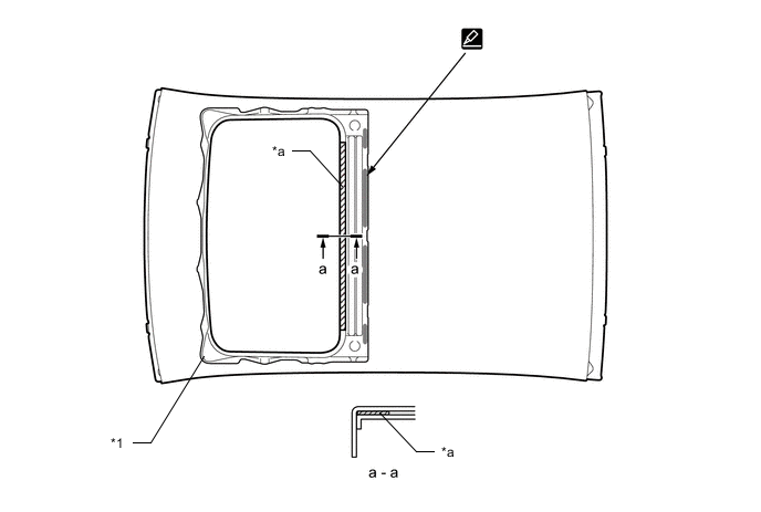
*1 ROOF PANEL REINFORCEMENT NO.2 - - *a Adhesive - - -
Before temporarily installing the new parts, weld the roof panel and roof panel reinforcement No.2 with the standard number of welding points.
-
Bend the flange hem with a wooden hammer and dolly.
Tech Tips
Bend the panel gradually so as not to distort it.
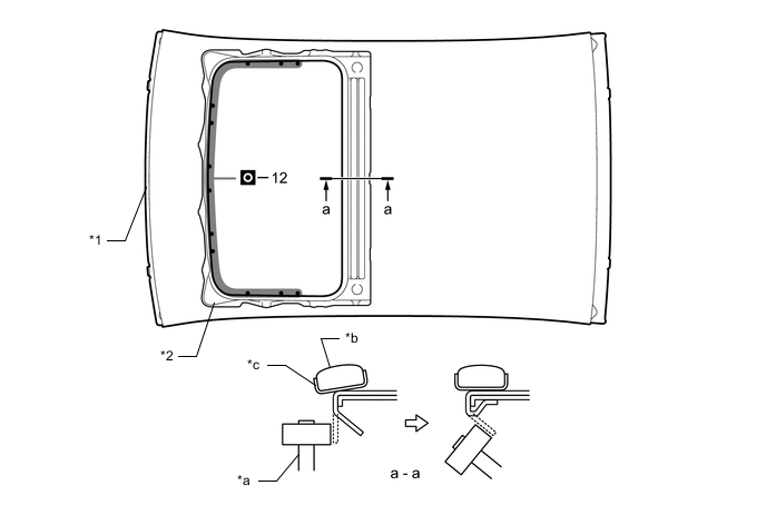
*1 ROOF PANEL *2 ROOF PANEL REINFORCEMENT NO.2 *a Wooden Hammer *b Dolly *c Cloth Tape - - -
Roof panel reinforcement No.1 installation.
-
Temporarily place the roof panel on the vehicle and fix the front and back in place using vise grip.
Tech Tips
Make sure to balance the roof panel lengthwise and widthwise.
-
Place marks on the roof side outer upper No.1 rail after aligning it with the roof panel reinforcement.
-
Remove the roof panel.
-
Align the roof panel reinforcement No.1 with the marks and perform welding.
Tech Tips
Push the protrusions against the roof side outer upper No.1 rail.
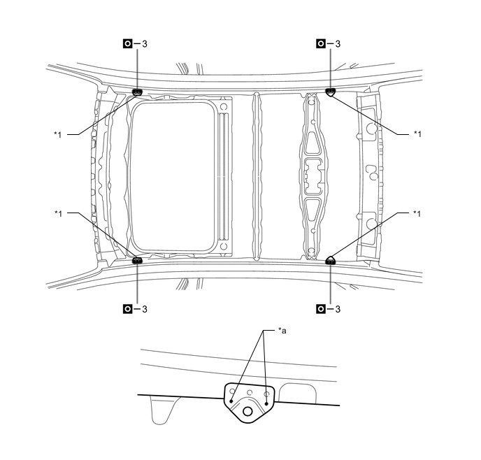
*1 ROOF PANEL REINFORCEMENT NO.1 - - *a Protrusions - -
-
-
Adjust the clearance between the roof panel reinforcement and roof panel reinforcement No.1.
-
Temporarily place the roof panel on the vehicle and fix the front and back in place using vise grip.
-
Make sure that *a (welded area) of the roof panel and roof panel reinforcement bracket do not interfere with the vehicle.
-
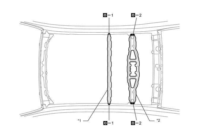
Visually make sure there is a clearance between the roof panel reinforcement and roof panel reinforcement No.1.
-
Visually make sure the clearance between the roof panel reinforcement and roof panel reinforcement No.1 is parallel.
Tech Tips
If the clearance is not parallel with the roof panel reinforcement No.1, lightly tap the roof panel reinforcement No.1 until it is parallel.
-
Measure the clearance labeled *b, and choose shims according to the chart.
Tech Tips
There are two types of shims: 0.5 mm and 1.0 mm
Clearance Shim 0.5 mm (0.020 in.) or less - 0.6 to 1.0 mm (0.024 to 0.039 in.) 0.5 mm (0.020 in.) 1.1 to 1.5 mm (0.043 to 0.059 in.) 1.0 mm (0.024 in.) 1.6 to 2.0 mm (0.063 to 0.079 in.) 0.5 + 1.0 mm (0.020 + 0.024 in.) 2.1 to 2.5 mm (0.083 to 0.098 in.) 1.0 + 1.0 mm (0.024 + 0.024 in.) 2.6 to 3.0 mm (0.102 to 0.118 in.) 0.5 + 1.0 + 1.0 mm (0.020 + 0.024 + 0.024 in.) 3.1 to 3.5 mm (0.122 to 0.138 in.) 1.0 + 1.0 + 1.0 mm (0.024 + 0.024 + 0.024 in.) -
Place shims in the clearance between the roof panel and roof panel reinforcement No.1 and tighten the bolts.
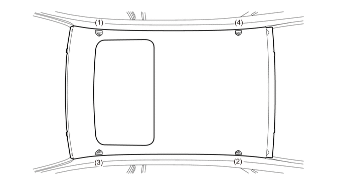
- Torque:
- 7.2 N*m { 73 kgf*cm, 64 in.*lbf }
Tech Tips
Be sure to tighten the bolts in diametric order.
-
*1 ROOF PANEL *2 ROOF SIDE OUTER UPPER NO.1 RAIL *3 Thickness Gauge After tightening all the bolts, check the contact points between the roof panel and roof side outer upper No.1 rail with a thickness gauge.
Tech Tips
-
If there is a difference between the left and right sides, confirm the roof panel installation and perform adjustment when necessary.
-
Change to a thinner shim if the roof panel changes when it is lightly pushed.
-
-
-
Remove the roof panel.
-
Weld the roof panel reinforcement No.7 and roof panel reinforcement No.4 to the vehicle side.
*1 ROOF PANEL REINFORCEMENT NO.7 *2 ROOF PANEL REINFORCEMENT NO.4 -
Remove the paint film where the adhesive will be applied for the roof panel and roof side outer upper No.1 rail.
Tech Tips
Do not remove the paint film where the roof drip moulding sub-assembly is installed.
-
Install the roof drip moulding sub-assembly.
*1 ROOF DRIP MOULDING SUB-ASSEMBLY *2 ROOF SIDE OUTER UPPER NO.1 RAIL *a Area to remove paint. - - Tech Tips
Do not install the roof drip moulding sub-assembly where the roof panel reinforcement No.1 is installed.
-
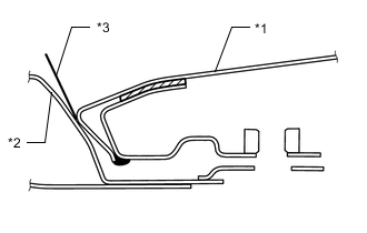
Apply adhesive.
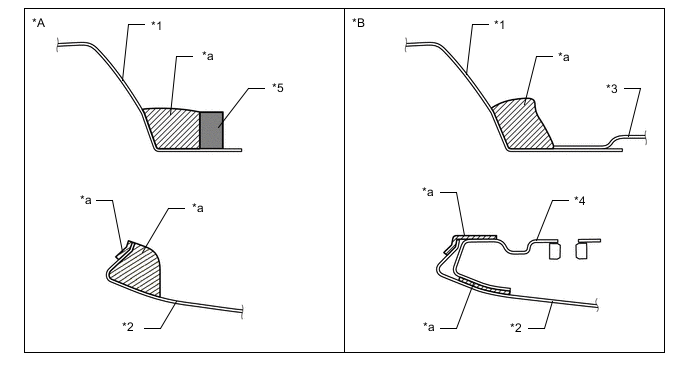
*A w/o ROOF PANEL REINFORCEMENT NO.1 *B w/ ROOF PANEL REINFORCEMENT NO.1 *1 ROOF SIDE OUTER UPPER NO.1 RAIL *2 ROOF PANEL *3 ROOF PANEL REINFORCEMENT NO.1 *4 ROOF PANEL REINFORCEMENT *5 ROOF DRIP MOULDING SUB-ASSEMBLY - - *a Adhesive - - -
Before temporarily installing the new parts, apply body sealer to the windshield header panel, roof panel reinforcement No.7, roof panel reinforcement No.4 and back window frame.
Tech Tips
Apply enough body sealer to the panels.
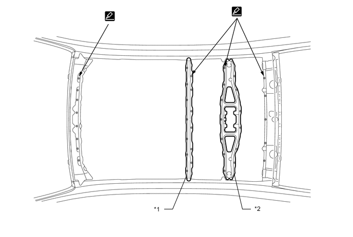
*1 ROOF PANEL REINFORCEMENT NO.7 *2 ROOF PANEL REINFORCEMENT NO.4
-
-
Roof panel installation.
-
Insert the shims selected during adjustment and install the bolts.
- Torque:
- 7.2 N*m { 73 kgf*cm, 64 in.*lbf }
Tech Tips
Be sure to tighten the bolts in diametric order.
-
Remove any protruding adhesive with a spatula.
Note
Do not remove too much adhesive.
-
Remove adhesive applied outside the application area before it hardens.
-
Weld the roof panel to the vehicle side.
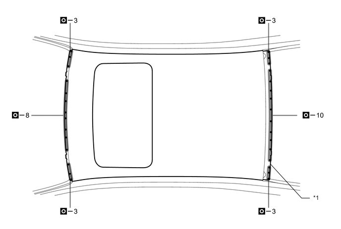
*1 ROOF PANEL - - -
*a Adhesive Apply adhesive inside the roof panel reinforcement.
-
-
Dry the adhesive areas of the new roof panel.
Tech Tips
-
With dryer or equivalent (60°C): 60 minutes (complete hardening: 90 minutes)
-
Ambient temperature (25°C): 12 hours (complete hardening: 24 hours)
-
-
Finishing.
-
Make a U shape using sand paper after the adhesive hardens.
-
Apply a small amount of sealer after making a U.
Tech Tips
If the adhesive finish looks good, it is not necessary to apply sealer.
-
-
After welding, apply the foamed sealing material to the corresponding parts. (See the painting/coating)
-
After welding, apply body sealer to the corresponding parts. (See the painting/coating)
-
After applying the top coat, apply anti-rust agent to the internal panel portion of the closed section structural weld points.
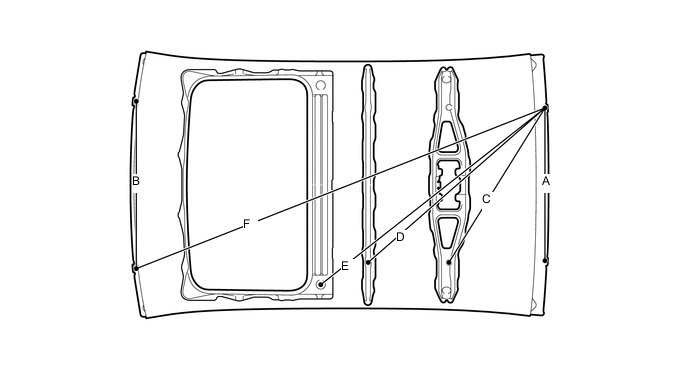
Reference Value: Area Measurement Area Measurement A 670 mm (26.38 in.) B 730 mm (28.74 in.) C 800 mm (31.50 in.) D 1034 mm (40.71 in.) E 1308 mm (51.50 in.) F 1926 mm (75.83 in.) -