FIT STANDARD / ADJUSTMENT METHOD ADJUSTMENT
-
INSPECT FITTING OF HOOD SUB-ASSEMBLY
-
Check that the clearance measurements of areas A to E are within the standard ranges.
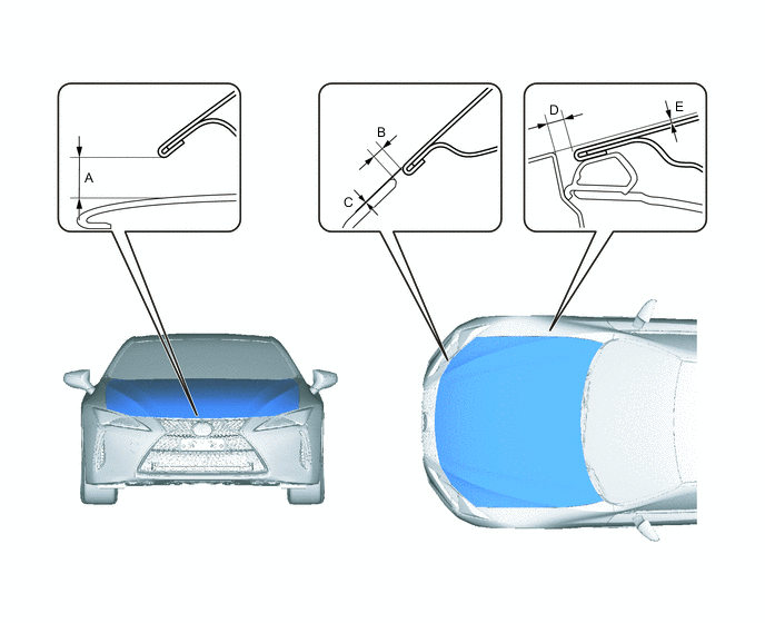
Tech Tips
Centering bolts are used to mount the hood hinge to the vehicle body and hood. The hood cannot be adjusted with the centering bolts on. Substitute the centering bolts for standard bolts (with washers) when making adjustments.
-
-
ADJUST HOOD SUB-ASSEMBLY
-
Adjust the hood position.
-
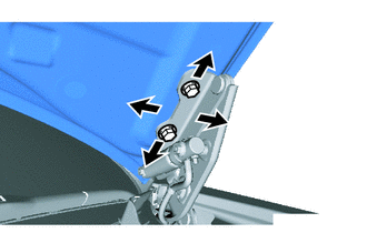
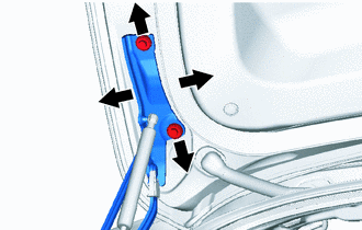
Loosen the 4 hinge bolts on the hood and adjust the hood position.
-
Move the hood and adjust the clearance between the hood and front fender.
-
Tighten the 4 hinge bolts on the hood after the adjustment.
- Torque:
- 13 N*m { 133 kgf*cm, 9.6 ft.*lbf }
-
-
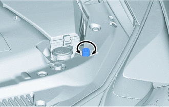
Adjust the height of the front end of the hood using the hood bumper cushions.
-
Adjust the 2 cushion rubbers so that the hood and fender are aligned.
Tech Tips
Raise or lower the front end of the hood by turning the 2 cushion rubbers.
-
-
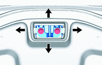
Adjust the hood lock.
-
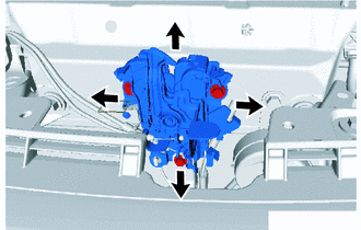
Loosen the 3 bolts.
-
Adjust the hood lock position so that the striker can enter it smoothly.
-
Tighten the 3 bolts after the adjustment.
- Torque:
- 8.0 N*m { 82 kgf*cm, 71 in.*lbf }
-
-
-
INSPECT FRONT DOOR LH
-
Check that the clearance measurements of areas A to G are within the standard ranges.
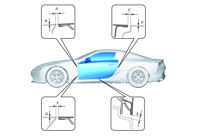
Standard Clearance: Area Specified Condition Area Specified Condition A 2.0 to 5.0 mm (0.079 to 0.197 in.) B -1.5 to 1.5 mm (-0.059 to 0.059 in.) C 2.0 to 5.0 mm (0.079 to 0.197 in.) D -1.5 to 1.5 mm (-0.059 to 0.059 in.) E 3.5 to 6.5 mm (0.138 to 0.256 in.) F 2.0 to 5.0 mm (0.079 to 0.197 in.) G -1.5 to 1.5 mm (-0.059 to 0.059 in.) - -
Tech Tips
-
Use the same procedure for the RH side and LH side.
-
The following procedure is for the LH side.
-
Centering bolts are used to mount the door hinge to the vehicle body and door. The door cannot be adjusted with the centering bolts installed. Substitute the centering bolts with standard bolts when making adjustments.
-
-
ADJUST FRONT DOOR LH
Note
Make sure to turn the engine switch off before adjusting the door lock strikers.
-
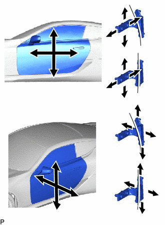
Using SST, loosen the hinge bolts on the body and adjust the door position.
- SST
- 09812-0010
-
Tighten the hinge bolts on the body after the adjustment.
- Torque:
- 32.5 N*m { 331 kgf*cm, 24 ft.*lbf }
-
Loosen the hinge bolts on the door and adjust the door position.
-
Tighten the hinge bolts on the door after the adjustment.
- Torque:
- 26 N*m { 265 kgf*cm, 19 ft.*lbf }
-
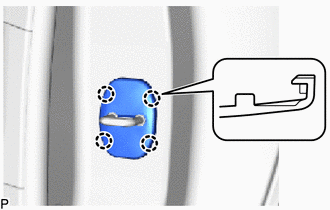
Detach the claws and remove the front door lock striker cover.
-
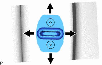
Using a T40 "TORX" socket, adjust the striker position by slightly loosening the striker mounting screws and hitting the striker with a brass bar and hammer.
- Torque:
- 23 N*m { 235 kgf*cm, 17 ft.*lbf }
-
Attach the claws to install the front door lock striker cover.
-
-
INSPECT LUGGAGE COMPARTMENT DOOR PANEL ASSEMBLY
-
Check that the clearance measurements of areas a through d are within each standard range.
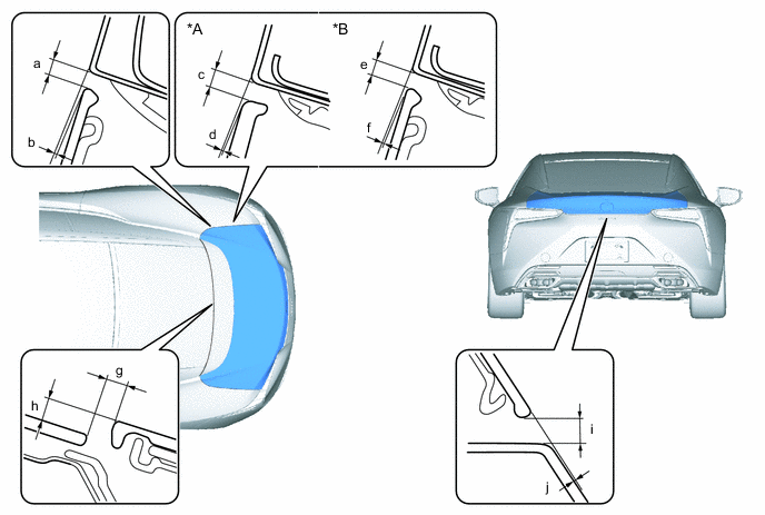
*A w/ Rear Active Wing *B w/o Rear Active Wing
Tech Tips
-
Use the same procedure for the RH side and LH side.
-
The procedure described below is for the LH side.
-
Centering bolts are used to mount the door hinge to the vehicle body and door. The door cannot be adjusted with the centering bolts installed. Substitute the centering bolts with standard bolts when making adjustments.
-
-
ADJUST LUGGAGE COMPARTMENT DOOR PANEL ASSEMBLY
-
Before adjusting the upper end of the back door up and down or left and right, loosen the bolts.
-
Tighten the hinge bolts on the body after the adjustment.
- Torque:
- 13 N*m { 133 kgf*cm, 10 ft.*lbf }
-
Adjust the striker position by slightly loosening the striker bolts and hitting the striker with a brass bar.
-
Tighten the striker bolts after the adjustment.
- Torque:
- 10 N*m { 102 kgf*cm, 7 ft.*lbf }
-