ENGINE COMPARTMENT THREE-DIMENSIONAL DISTANCE
Tech Tips
-
In cases in which only one dimension is given, left and right are symmetrical.
-
For symbols, capital letters indicate right side of vehicle, small letters indicate left side of vehicle (seen from rear).
| Symbol | Name | Hole Diameter mm (in.) |
|---|---|---|
| A, a | Front Fender Installation Nut | M6 (0.24) |
| B, b | Front Fender Installation Nut | M6 (0.24) |
| C, c | Front Fender Installation Nut | M6 (0.24) |
| D | Cowl Top Panel Center Mark | - |
| E, e | Front Side Member Standard Hole | φ13 (0.51) |
| F, f | Front Spring Support Installation Hole | φ12.5 (0.49) |
| G, g | Front Side Member Standard Hole | φ15 (0.59) |
| H, h | Radiator Support Upper Installation Nut | M6 (0.24) |
| J, j | Front Bumper Mounting Reinforcement Installation Nut | M12 (0.47) |
| K, k | Front Bumper Mounting Reinforcement Installation Nut | M12 (0.47) |
| L | Hood Lock Support Brace Installation Nut | M6 (0.24) |
| M, m | Radiator Support to Front Fender Bracket Standard Hole | φ15 (0.59) |
| N, n | Radiator Support Upper Installation Nut | M6 (0.24) |
| O, o | Radiator Upper Support Standard Hole | φ10 (0.39) |
| P, p | Outrigger No.1 Installation Bolt | M6 (0.24) |
| Q, q | Outrigger No.1 Installation Bolt | M6 (0.24) |
| R, r | Cowl Top Side Panel Standard Hole | φ10 (0.39) |
| S, s | Hood Hinge Installation Nut | M8 (0.31) |
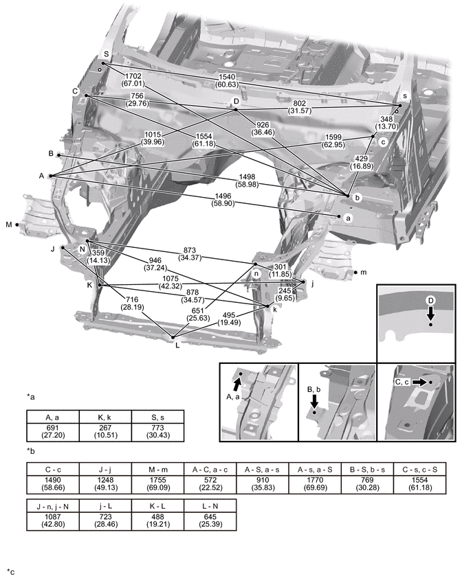
| *a | Height from Imaginary Datum Line | *b | Distance between points other than those above |
| *c | mm (in.) |
- | - |
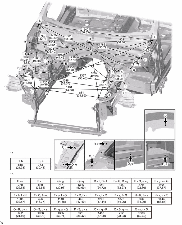
| *a | Height from Imaginary Datum Line | *b | Distance between points other than those above |
| *c | mm (in.) |
- | - |