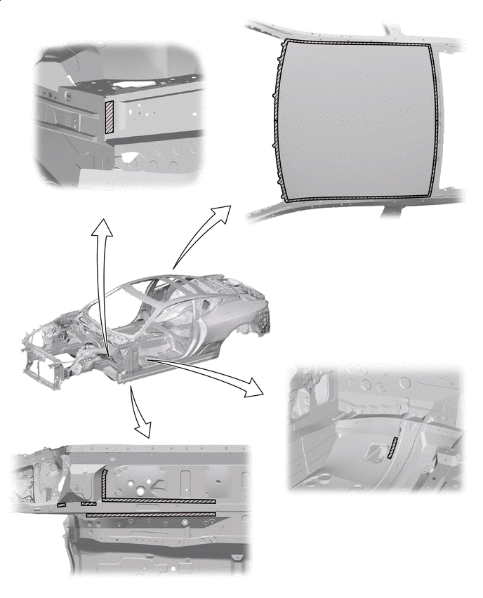
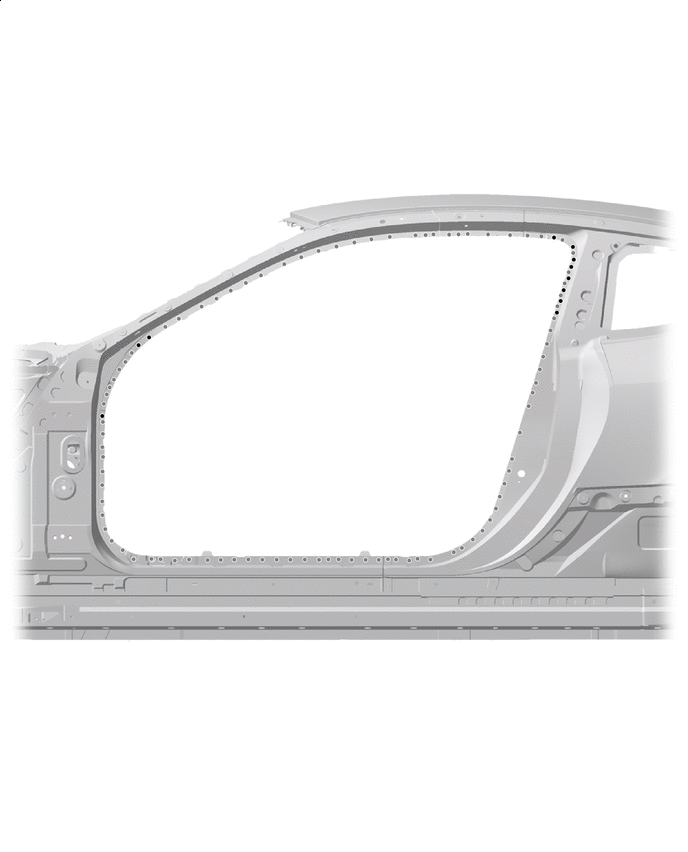
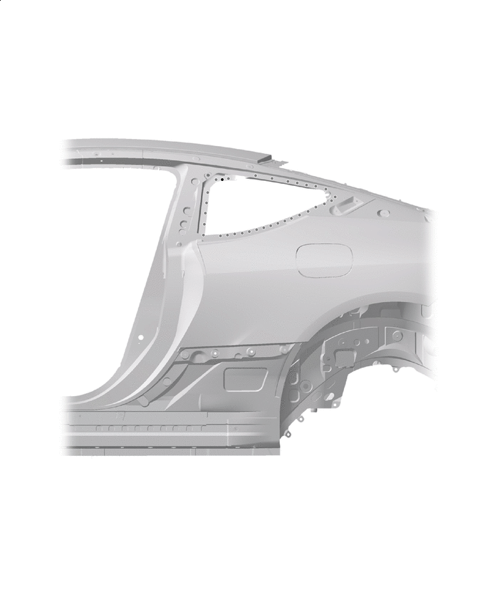
ABOUT THIS VEHICLE STRUCTURAL OUTLINE
 |
1500 MPa Ultra High Strength Steel |  |
1180 MPa Ultra High Strength Steel |
 |
980 MPa Ultra High Strength Steel |  |
780 MPa Ultra High Strength Steel |
 |
590 MPa High Strength Steel |  |
440 MPa High Strength Steel |
 |
Aluminum | - | - |
| |
1180 MPa Ultra High Strength Steel | |
980 MPa Ultra High Strength Steel |
| |
780 MPa Ultra High Strength Steel | |
590 MPa High Strength Steel |
| |
440 MPa High Strength Steel | |
Aluminum |

| |
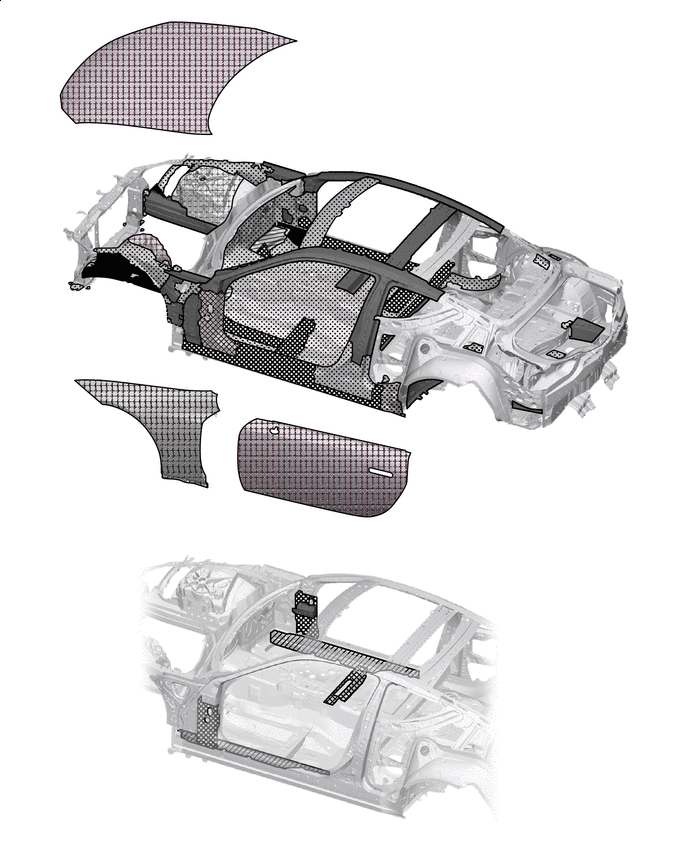
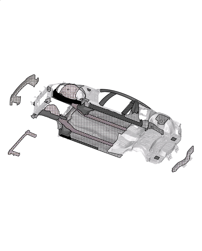
Foamed Sealing Material Application Areas (See the painting/coating) | - | - |
 |
Adhesive Application Areas | - | - |
| |
Adhesive Application Areas | - | - |
| |
Adhesive Application Areas | - | - |

| |
Adhesive Application Areas | - | - |
| |
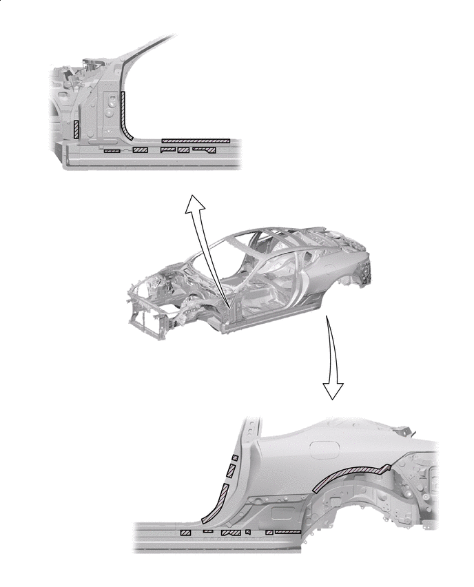
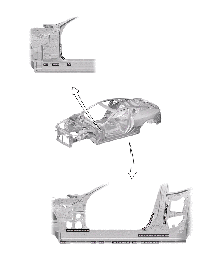
Laser Screw Welding | |
Spot Welding |
| |
Laser Screw Welding | |
Spot Welding |
| |
Laser Screw Welding | |
Spot Welding |
| |
Laser Screw Welding | |
Spot Welding |
-
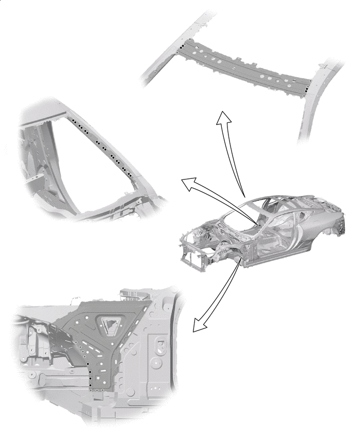
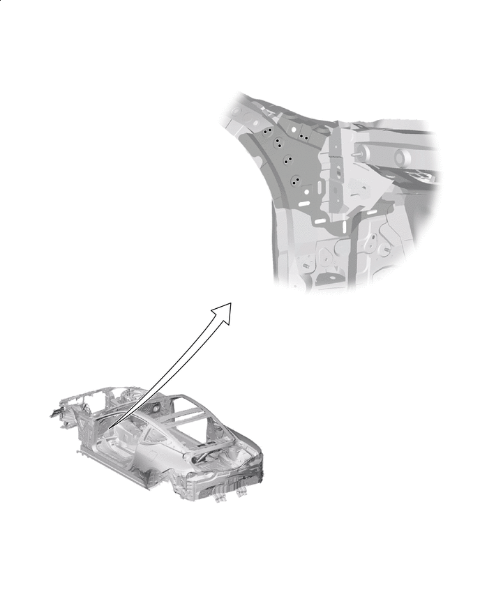
STRUCTURAL OUTLINE OF FRONT FENDER APRON ASSEMBLY
-
Suspension tower of aluminum die casting improves exercise performance (weight reduction/low center of gravity/high rigidity).
-
Aluminum die casting and steel plate are fastened by SPR (Self Pierce Rivet). (SPR: 43 places)
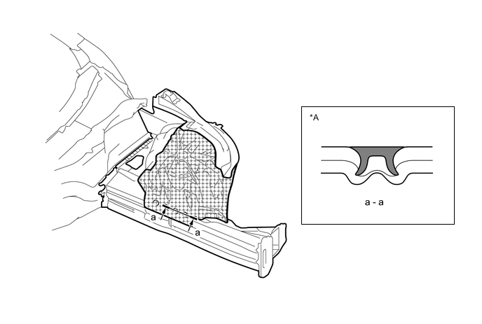
*A Cross section of SPR fastening - - Aluminum die casting - -
-
-
Notes on supply form and repair
-
Main components of the front fender apron assy (supply form) (*1, *2, *3, *4 also have single item supply)
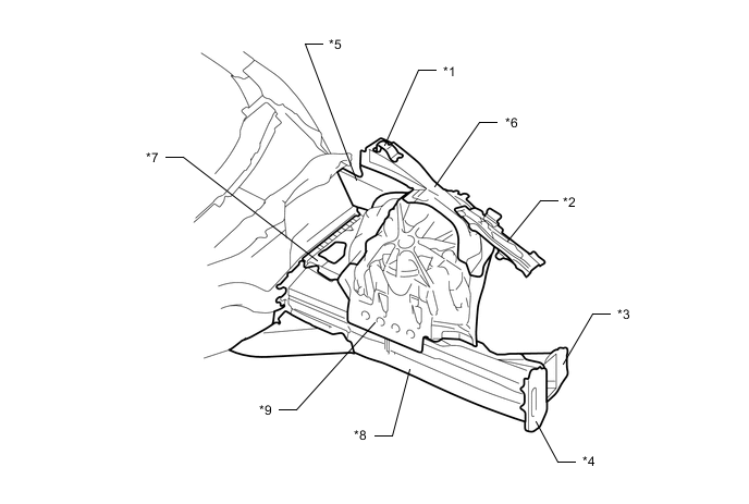
*1 FENDER APRON PLATE *2 NO.1 RH OUTRIGGER SUB-ASSEMBLY *3 OUTRIGGER GUSSET NO.1 *4 FRONT BUMPER ARM SUPPORT *5 COWL TOP SIDE PANEL *6 FRONT FENDER TO COWL SIDE MEMBER *7 FRONT FENDER REAR APRON *8 FRONT SIDE MEMBER *9 SUSPENSION TOWER - - -
Repair of the front fender apron assy
Note
-
Do not repair (remove/install) the SPR fastening.
-
Do not repair aluminum die casting.
-
Do not cut and join repair side member(780MPa).
COMPONENT PART PARTS No. SPR FASTENING SINGLE ITEM EXCHANGE CORRECTION OF STEEL PLATE FENDER APRON PLATE 53717/8- None Possible as usual NO.1 RH OUTRIGGER SUB-ASSEMBLY 57301/2- OUTRIGGER GUSSET NO.1 57337/8- FRONT BUMPER ARM SUPPORT 57141/2- COWL TOP SIDE PANEL - use impossible *a FRONT FENDER TO COWL SIDE MEMBER - FRONT FENDER REAR APRON - FRONT SIDE MEMBER - *a, *b SUSPENSION TOWER - Aluminum die casting
*c
*a:
Minor damage (such as end flange deformation and slight distortion) can be corrected.
*b:
When using a frame aligner, be sure to check looseness of SPR. (SPR may be loose.)
Due to its high rigidity, large damage (folding or clear bending) can not be corrected.
*c:
Do not repair die casting
-
-
-
-
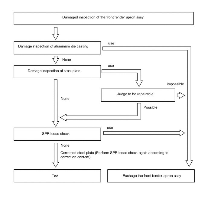
NECESSITY OF EXCHANGE OF THE FRONT FENDER APRON ASSY AND DAMAGE CHECK OF SPR FASTENING PART
-
If there is a possibility of receiving an impact on the SPR fastening part, looseness check of SPR is performed by the following procedure.
-
Input to the SPR fastening part is [input from the steel plate side] and [input from the aluminum die cast side].
-
If the SPR is loose, it is necessary to replace the front fender apron assy.
-
-
Procedure of SPR loose check
-
The SPR fastening part is covered with a paint film and body sealer.
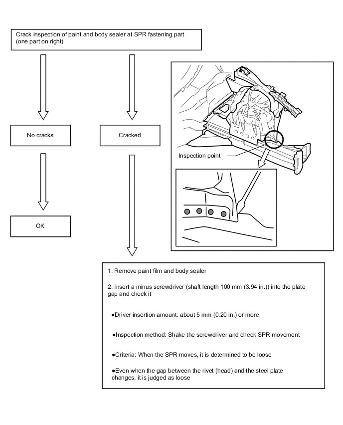
-
-