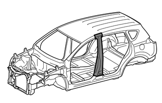
CENTER BODY PILLAR CUT AND JOIN REPLACEMENT SECTIONS
-
REMOVAL
Symbol Meaning 
Remove Weld Points 
Cut and Join Location 
Cut Location for Supply Parts
-
Do not butt weld or heat repair because the heat decreases the strength of areas where ultra high strength steel is used. (See the introduction)
-
Reuse A, as the area of the outer panel that is cut and joined is above the supplied part cut position.
*a 20 mm (0.79 in.) *b 200 mm (7.87 in.) *c 90 mm (3.54 in.) - - 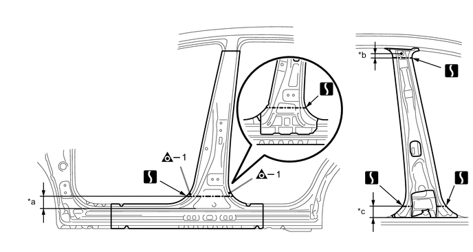
*a 80 mm (3.15 in.) *b 20 mm (0.79 in.) *c 75 mm (2.95 in.) - - 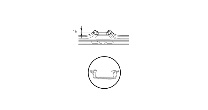
*a 40 mm (1.57 in.) - - -
When replace only the outer panel, please cut off a necessary range depending on a damage range.
-
Carefully cut the outer panel so not to damage the reinforcement.
-
Make sure that butt welding does not heat-affect the reinforcement when welding the outer panel.
-
-
-
INSTALLATION
Symbol Meaning 
Spot Weld 
Plug Weld Cut and Join Location 
Butt Weld
-
Inspect the fitting of the related parts around the new parts before welding. This affects the appearance of the finish.
-
Temporarily install the new parts and measure each part of the new parts in accordance with the body dimension diagram. (See the body dimensions)
-
If the entire supply part is not needed, remove the part of the supply part that is needed.
Tech Tips
-
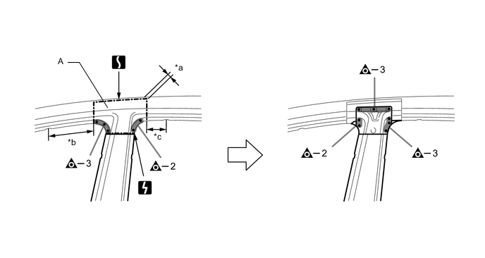
Carefully cut the center body pillar reinforcement sub-assembly so not to damage A.
-
Carefully cut the No.4 inner pillar sub-assembly so not to damage B.
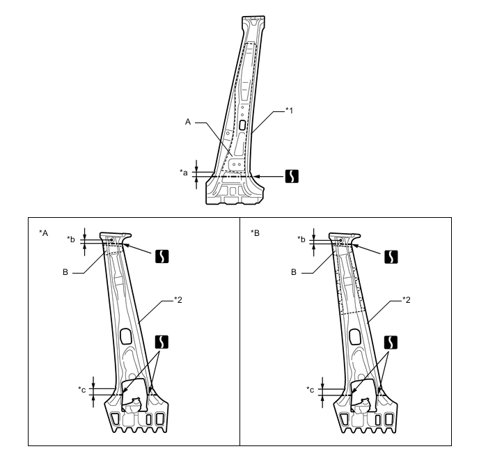
*A except Korea *B for Korea *1 CENTER BODY PILLAR REINFORCEMENT SUB-ASSEMBLY *2 NO.4 INNER PILLAR SUB-ASSEMBLY *a 30 mm (1.18 in.) *b 20 mm (0.79 in.) *c 45 mm (1.77 in.) - - -
-
Before temporarily installing the new parts, weld the center body pillar reinforcement sub-assembly and No.4 inner pillar sub-assembly with the standard number of welding points.
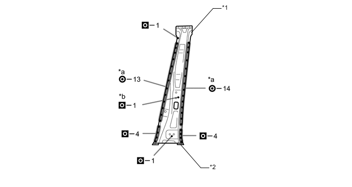
*1 CENTER BODY PILLAR REINFORCEMENT SUB-ASSEMBLY *2 NO.4 INNER PILLAR SUB-ASSEMBLY *a Ultra High Strength Steel Welding Point *b Ultra High Strength Steel Welding Point
-
When welding 2 panels together including 980 MPa ultra high strength steel.
*a: Spot weld Pressure 2940 N (300 kgf, 661 lbf) Weld current 10000 A Weld time 18 Cyc. (0.30 Sec.) *b: Plug weld Plug diameter 10 mm (0.39 in.) Wire type AWS A5.18 ER70S-3 Shield gas Metal active gas Note
Be sure to use Metal active gas (Ar 80% + CO220%) as the shield gas when plug welding.Sufficient weld strength cannot be assured when using 100% CO2shield gas.
Follow the welding conditions below when welding ultra high strength steel to assure sufficient weld strength. (When repairing this model)
-
-
Weld the center body pillar reinforcement sub-assembly and No.4 inner pillar sub-assembly to the vehicle side.
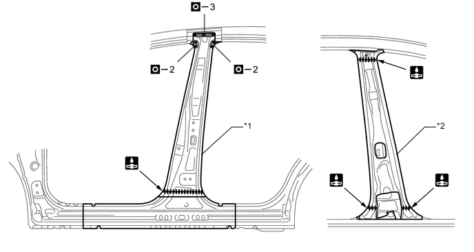
*1 CENTER BODY PILLAR REINFORCEMENT SUB-ASSEMBLY *2 NO.4 INNER PILLAR SUB-ASSEMBLY -
Weld the center body pillar outer and A to the vehicle side.
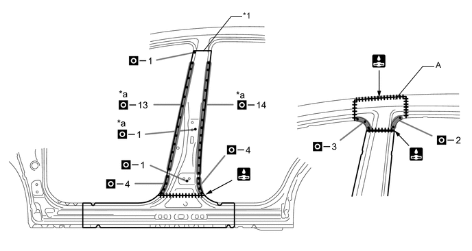
*1 CENTER BODY PILLAR OUTER - - *a Ultra High Strength Steel Welding Point - -
-
When welding more than 3 panels together including 980 MPa ultra high strength steel. (When plug welding a third panel to 2 panels which are welded under the conditions described above.)
*a: Plug weld Plug diameter Same as the standard method (See the introduction) Wire type AWS A5.18 ER70S-3 Shield gas Metal active gas Note
Be sure to use Metal active gas (Ar 80% + CO220%) as the shield gas when plug welding.Sufficient weld strength cannot be assured when using 100% CO2shield gas.
Follow the welding conditions below when welding ultra high strength steel to assure sufficient weld strength. (When repairing this model)
-
-
After welding, apply the foamed sealing material to the corresponding parts. (See the painting/coating)
-
After applying the top coat, apply anti-rust agent to the internal panel portion of the closed section structural weld points.
-