FIT STANDARD / ADJUSTMENT METHOD ADJUSTMENT
-
INSPECT HOOD SUB-ASSEMBLY
-
Check that the clearance measurements of areas A to H are within the standard ranges.
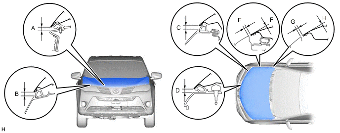
Standard Clearance Area Measurement Area Measurement A
(Reference)
4.6 to 9.6 mm (0.181 to 0.378 in.) B
(Reference)
5.3 to 10.3 mm (0.209 to 0.406 in.) C
(Reference)
5.4 to 10.4 mm (0.213 to 0.409 in.) D
(Reference)
4.7 to 9.7 mm (0.185 to 0.382 in.) E 1.7 to 4.7 mm (0.0669 to 0.185 in.) F -1.5 to 1.5 mm (-0.0591 to 0.0591 in.) G 1.7 to 4.7 mm (0.0669 to 0.185 in.) H -1.5 to 1.5 mm (-0.0591 to 0.0591 in.)
Tech Tips
Centering bolts are used to mount the hood hinge to the vehicle body and hood. The hood cannot be adjusted with the centering bolts on. Substitute the centering bolts for standard bolts (with washers) when making adjustments.
-
-
ADJUST HOOD SUB-ASSEMBLY
-
Adjust the hood position.
-
Loosen the 4 hinge bolts on the hood and adjust the hood position.
-
Move the hood and adjust the clearance between the hood and front fender.
-
Tighten the 4 hinge bolts on the hood after the adjustment.
- Torque:
- 13 N*m { 133 kgf*cm, 9.6 ft.*lbf }
-
-
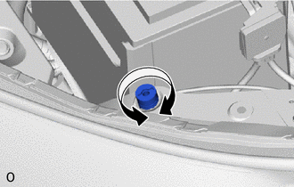
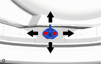
Adjust the cushion rubbers so that the hood and fender are aligned.
Tech Tips
Raise or lower the front end of the hood by turning the cushion rubber.
-
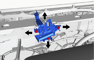
Adjust the hood lock.
-
Loosen the 3 bolts.
-
Adjust the hood lock position so that the striker can enter it smoothly.
-
Tighten the 3 bolts after the adjustment.
- Torque:
- 8.0 N*m { 82 kgf*cm, 71 in.*lbf }
-
-
-
INSPECT FRONT DOOR PANEL SUB-ASSEMBLY LH
-
Check that the clearance measurements of areas A to L are within the standard ranges.
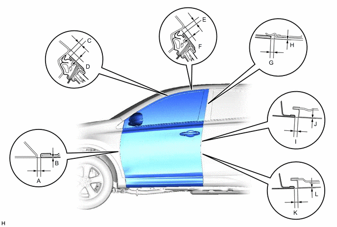
Standard Clearance Area Measurement Area Measurement A 2.2 to 5.2 mm (0.0866 to 0.205 in.) B -1.5 to 1.5 mm (0.0591 to 0.0591 in.) C 3.7 to 6.7 mm (0.146 to 0.264 in.) D 4.5 to 7.5 mm (0.177 to 0.295 in.) E 3.7 to 6.7 mm (0.146 to 0.264 in.) F 4.2 to 7.2 mm (0.165 to 0.283 in.) G
(Reference)
2.5 to 6.5 mm (0.0984 to 0.259 in.) H -2.0 to 2.0 mm (-0.0787 to 0.0787 in.) I 2.9 to 5.3 mm (0.114 to 0.209 in.) J -1.2 to 1.2 mm (-0.0472 to 0.0472 in.) K 2.9 to 5.3 mm (0.114 to 0.209 in.) L -1.2 to 1.2 mm (-0.0472 to 0.0472 in.)
Tech Tips
-
Use the same procedure for the RH and LH sides.
-
The procedure listed below is for the LH side.
-
Centering bolts are used to mount the door hinge to the vehicle body and door. The door cannot be adjusted with the centering bolts on. Substitute the centering bolts for standard bolts when making adjustments.
-
-
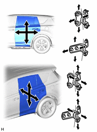
ADJUST FRONT DOOR PANEL SUB-ASSEMBLY LH
-
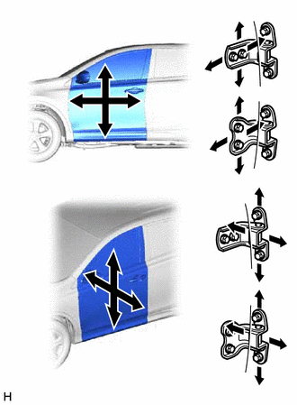
Using SST, loosen the hinge bolts on the body and adjust the door position.
- SST
- 09812-00010
-
Tighten the hinge bolts on the body after the adjustment.
- Torque:
- 26 N*m { 265 kgf*cm, 19 ft.*lbf }
-
Loosen the hinge bolts on the door and adjust the door position.
-
Tighten the hinge bolts on the door after the adjustment.
- Torque:
- 26 N*m { 265 kgf*cm, 19 ft.*lbf }
-
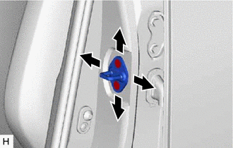
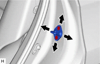
Using a T40 "TORX" socket, adjust the striker position by slightly loosening the striker mounting screws and hitting the striker with a plastic-faced hammer.
-
Using a T40 "TORX" socket, tighten the striker mounting screws after the adjustment.
- Torque:
- 23 N*m { 235 kgf*cm, 17 ft.*lbf }
-
-
INSPECT REAR DOOR PANEL SUB-ASSEMBLY LH
-
Check that the clearance measurements of areas A to L are within the standard ranges.
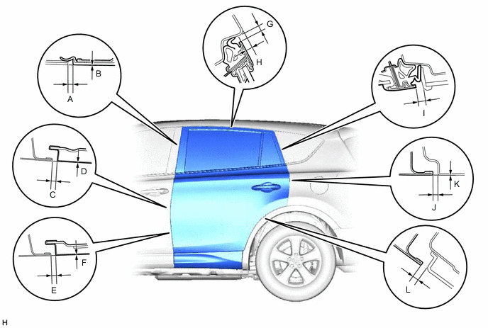
Standard Clearance Area Measurement Area Measurement A
(Reference)
2.5 to 6.5 mm (0.0866 to 0.205 in.) B -2.0 to 2.0 mm (-0.0787 to 0.0787 in.) C 2.9 to 5.3 mm (0.114 to 0.209 in.) D -1.2 to 1.2 mm (-0.0472 to 0.0472 in.) E 2.9 to 5.3 mm (0.114 to 0.209 in.) F -1.2 to 1.2 mm (-0.0472 to 0.0472 in.) G 3.9 to 6.9 mm (0.154 to 0.272 in.) H 3.2 to 6.2 mm (0.126 to 0.244 in.) I
(Reference)
4.6 to 7.6 mm (0.181 to 0.299 in.) J 3.7 to 6.7 mm (0.146 to 0.264 in.) K -1.5 to 1.5 mm (-0.0591 to 0.0591 in.) L
(Reference)
4.9 mm (0.193 in.)
Tech Tips
-
Use the same procedure for the RH and LH sides.
-
The procedure listed below is for the LH side.
-
Centering bolts are used to mount the door hinge to the vehicle body and door. The door cannot be adjusted with the centering bolts on. Substitute the centering bolts for standard bolts when making adjustments.
-
-
ADJUST REAR DOOR PANEL SUB-ASSEMBLY LH
-
Loosen the hinge bolts on the body and adjust the door position.
-
Tighten the hinge bolts on the body after the adjustment.
- Torque:
- 26 N*m { 265 kgf*cm, 19 ft.*lbf }
-
Loosen the hinge bolts on the door and adjust the door position.
-
Tighten the hinge bolts on the door after the adjustment.
- Torque:
- 26 N*m { 265 kgf*cm, 19 ft.*lbf }
-
Using a T40 "TORX" socket, adjust the striker position by slightly loosening the striker mounting screws and hitting the striker with a plastic-faced hammer.
-
Using a T40 "TORX" socket, tighten the striker mounting screws after the adjustment.
- Torque:
- 23 N*m { 235 kgf*cm, 17 ft.*lbf }
-
-
INSPECT BACK DOOR PANEL SUB-ASSEMBLY
-
Check that the clearance measurements of areas A to G are within the standard ranges.
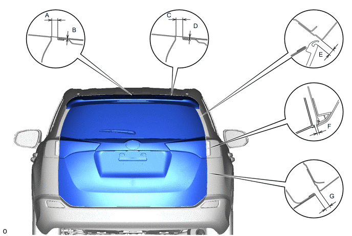
Standard Clearance Area Measurement Area Measurement A 6.0 to 9.0 mm (0.236 to 0.354 in.) B -0.5 to 2.5 mm (0.0196 to 0.0984 in.) C 6.0 to 9.0 mm (0.236 to 0.354 in.) D -0.5 to 2.5 mm (0.0196 to 0.0984 in.) E
(Reference)
3.35 to 7.35 mm (0.132 to 0.290 in.) F
(Reference)
3.5 to 7.5 mm (0.138 to 0.295 in.) G 3.7 to 6.7 mm (0.147 to 0.264 in.) - -
Tech Tips
-
Use the same procedure for the RH and LH sides.
-
The procedure listed below is for the RH side.
-
Centering bolts are used to mount the door hinge to the vehicle body and door. The door cannot be adjusted with the centering bolts on. Substitute the centering bolts for standard bolts when making adjustments.
-
-
ADJUST BACK DOOR PANEL SUB-ASSEMBLY
-
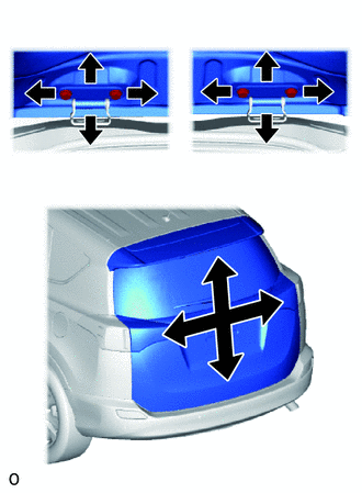
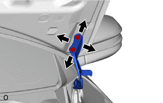
Before adjusting the upper end of the back door up and down or left and right, loosen the bolts.
-
Tighten the hinge bolts on the body after the adjustment.
- Torque:
- 20 N*m { 204 kgf*cm, 15 ft.*lbf }
-
Using a T40 "TORX" socket, adjust the striker position by slightly loosening the striker mounting screws and hitting the striker with a plastic-faced hammer.
-
Using a T40 "TORX" socket, tighten the striker mounting screws after the adjustment.
- Torque:
- 23 N*m { 235 kgf*cm, 17 ft.*lbf }
-