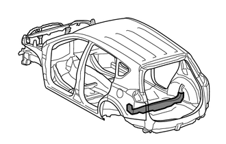
REAR FLOOR UPPER CENTER CROSSMEMBER ASSEMBLY REPLACEMENT
-
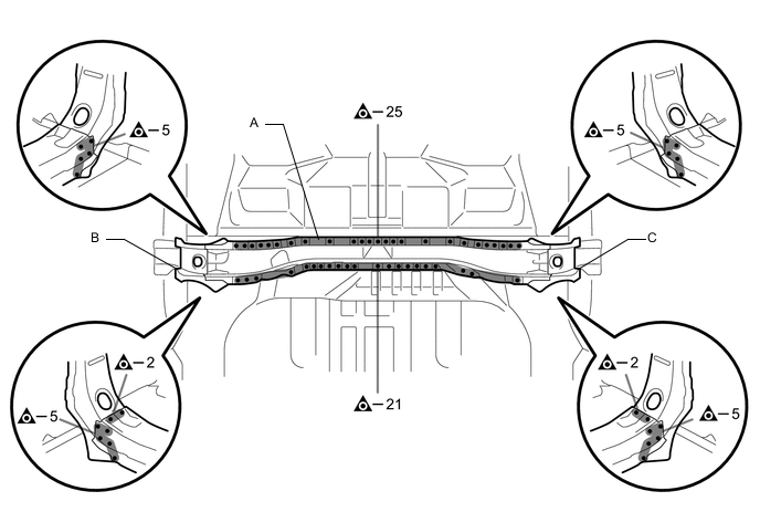
REMOVAL
Symbol Meaning 
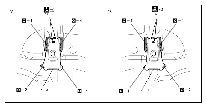
Remove Weld Points 
Cut with Disc Sander etc.
-
After removing the A, remove the B and C.
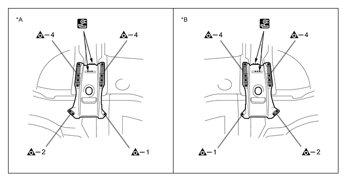
*A LH Side *B RH Side
-
-
INSTALLATION
Symbol Meaning Remove Weld Points 
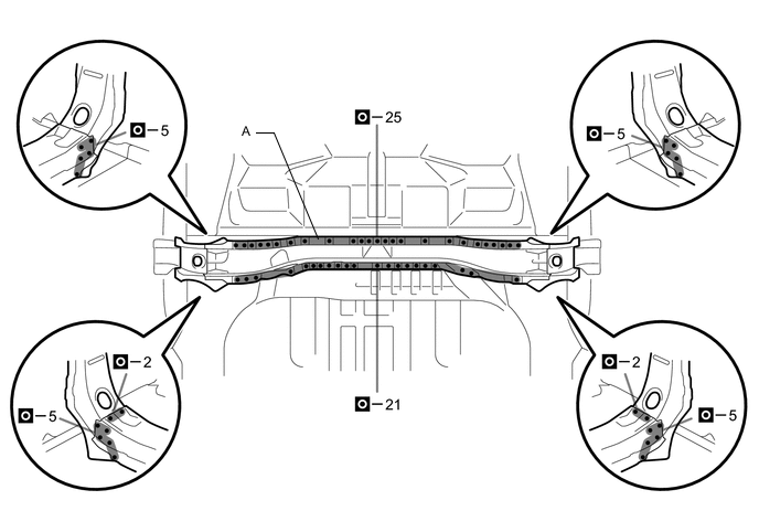
Plug Weld 
Fillet Weld
-
Temporarily install the new parts and measure each part of the new parts in accordance with the body dimension diagram. (See the body dimensions)
-
Remove A, B and C from the new parts.
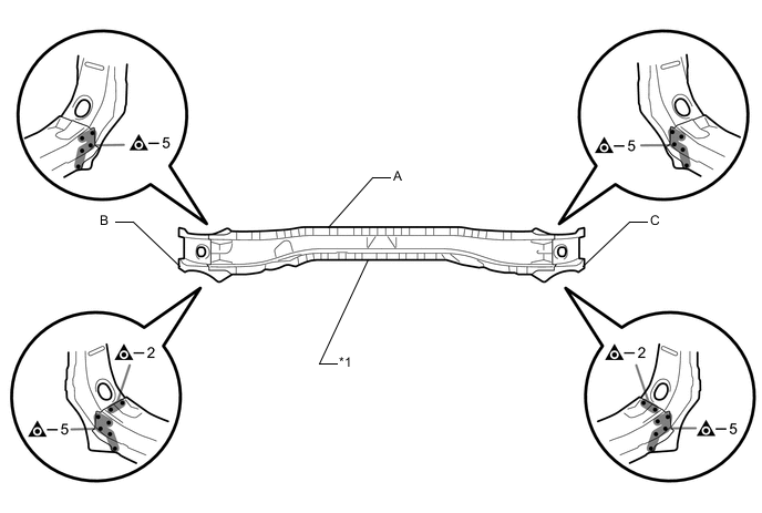
*1 SIDE MEMBER TO FLOOR REINFORCE SUB-ASSEMBLY - - -
Weld the A and B to the vehicle side.
*A LH Side *B RH Side *a 20 mm (0.79 in.) - - -
Weld the A to the vehicle side.
-
After welding, apply body sealer to the corresponding parts. (See the painting/coating)
-
After applying the top coat, apply anti-rust agent to the internal panel portion of the closed section structural weld points.
-