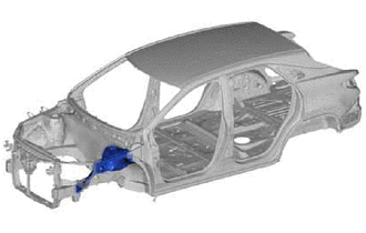
FRONT FENDER APRON ASSEMBLY REPLACEMENT
-
With the radiator side support assembly and cowl top side panel assembly removed.
-
REMOVAL
Symbol meaning 
Remove Weld Points 
Remove Weld Points 
Remove Weld Points 
Cut with Disc Sander etc. 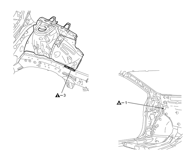
-
Roughly cut open the panel so that the adhesive can be reached. Cut through the adhesive with a cut chisel to remove the panel.
Tech Tips
In cases where the adhesive cannot be removed with a cut chisel, heat the adhesive with an industrial heater gun or gas burner taking care not to cause panel deformation by overheating.

Adhesive - -
-
-
INSTALLATION
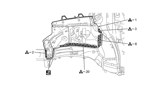
Symbol meaning 
Plug Weld 
Plug Weld 
Plug Weld 
Fillet Weld
-
Inspect the fitting of the related parts around the new parts before welding. This affects the appearance of the finish.
-
Temporarily install the new parts and measure each part of the new parts in accordance with the body dimension diagram. (See the body dimensions)
-
Apply adhesive (3MTMAutomixTMPanel Bonding Adhesive #8115).
Tech Tips
-
Apply a light coat of adhesive around the plug welding points.
-
Apply enough adhesive to the panels.

Adhesive - - -
-
Make sure to attach correctly in accordance with the body dimension diagram as this part affects the front wheel alignment.
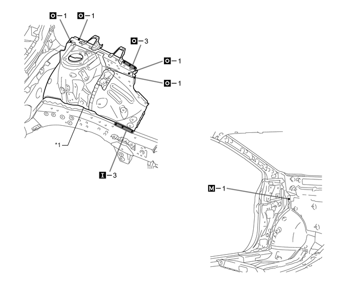
*1 FRONT FENDER APRON SUB-ASSEMBLY - - 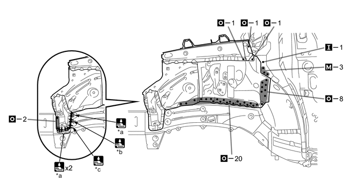
*a 6 mm (0.24 in.) *b 14 mm (0.55 in.) *c 12 mm (0.47 in.) - - -
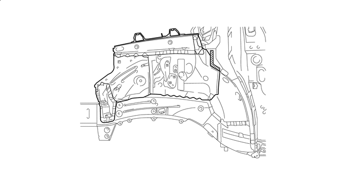
After welding, apply body sealer and undercoating to the corresponding parts. (See the painting / coating)
-
After applying the top coat, apply anti-rust agent to the internal panel portion of the closed section structural weld points.
-