FIT STANDARD / ADJUSTMENT METHOD ADJUSTMENT
-
INSPECT HOOD SUB-ASSEMBLY
-
Check that the clearance measurements of areas a through c are within each standard range.
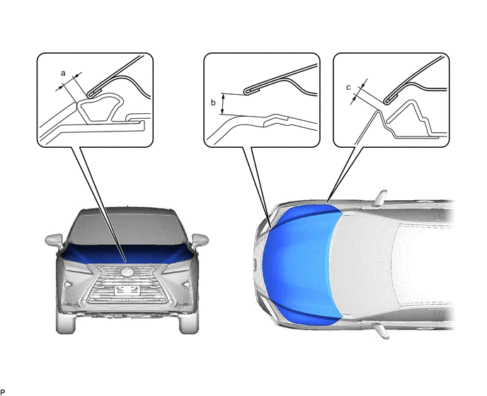
Standard Clearance Area Measurement Area Measurement a 2.95 to 5.95 mm (0.116 to 0.234 in.) b 8.15 mm (0.321 in.) c 5.25 mm (0.207 in.) - - Tech Tips
Centering bolts are used to install the hood hinges and hood lock. The hood and hood lock cannot be adjusted with the centering bolts installed. Substitute the centering bolts with standard bolts (with washers) when making adjustments.
-
-
ADJUST HOOD SUB-ASSEMBLY
-
Horizontally and vertically adjust the hood.
-
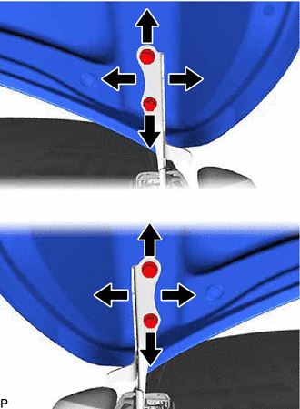
Loosen the 4 hinge bolts of the hood.
-
Adjust the clearance between the hood and front fenders by moving the hood.
-
Tighten the 4 hinge bolts after adjustment.
- Torque:
- 13 N*m { 133 kgf*cm, 10 ft.*lbf }
-
-
Adjust the height of the front end of the hood using the hood bumper cushions.
-
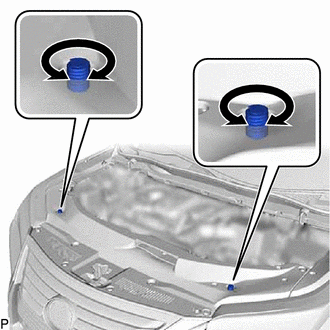
Adjust the 2 hood bumper cushions so that the heights of the hood and fenders are aligned.
Tech Tips
Raise or lower the front end of the hood by turning the 2 hood bumper cushions.
-
-
Adjust the hood lock.
-
Remove the cool air intake duct seal.
-
Remove the hood lock release lever protector.
-
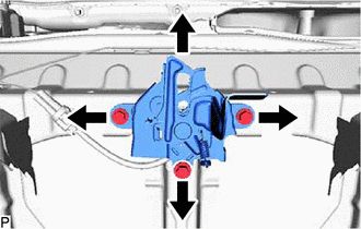
Loosen the 3 bolts.
-
Adjust the hood lock and tighten the 3 bolts.
- Torque:
- 8.0 N*m { 82 kgf*cm, 71 in.*lbf }
-
Check that the striker can engage the hood lock smoothly.
-
Install the hood lock release lever protector.
-
Install the cool air intake duct seal.
-
-
-
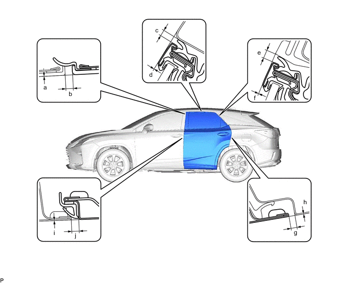
INSPECT FRONT DOOR
-
Check that the clearance measurements of areas a through l are within each standard range.
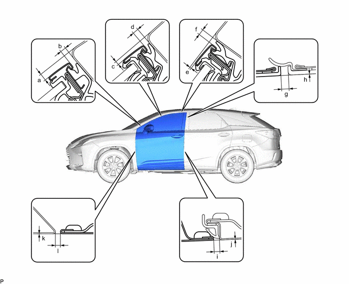
Standard Clearance Area Measurement Area Measurement a 3.6 to 6.6 mm (0.142 to 0.26 in.) b 4.4 to 7.4 mm (0.173 to 0.291 in.) c 0.9 to 3.9 mm (0.0354 to 0.154 in.) d 3.5 to 6.5 mm (0.138 to 0.256 in.) e -0.1 to 2.9 mm (-0.00394 to 0.114 in.) f 3.5 to 6.5 mm (0.138 to 0.256 in.) g 2.1 to 6.1 mm (0.0827 to 0.240 in.) h -2.0 to 2.0 mm (-0.0787 to 0.0787 in.) i 2.3 to 4.7 mm (0.0906 to 0.185 in.) j -1.2 to 1.2 mm (-0.0472 to 0.0472 in.) k -1.5 to 1.5 mm (-0.0591 to 0.0591 in.) l 2.0 to 5.0 mm (0.0787 to 0.197 in.) Tech Tips
-
Use the same procedure for the RH side and LH side.
-
The following procedure is for the LH side.
-
Centering bolts are used to install the door hinges to the vehicle body and door. The door cannot be adjusted with the centering bolts installed. Substitute the centering bolts with standard bolts when making adjustments.
-
-
-
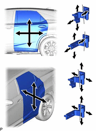
ADJUST FRONT DOOR
Note
Make sure to turn the ignition switch off when adjusting door lock strikers.
-
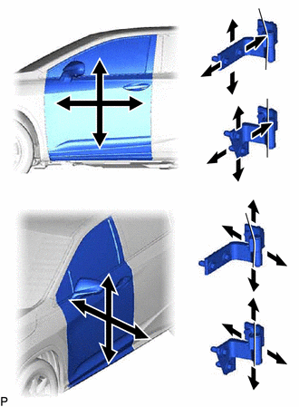
Using SST, loosen the 2 hinge bolts on the vehicle body and adjust the door position.
- SST
- 09812-00020
-
Tighten the 4 hinge bolts on the vehicle body after adjustment.
- Torque:
- 32.5 N*m { 331 kgf*cm, 24 ft.*lbf }
-
Loosen the 4 hinge bolts on the door and adjust the door position.
-
Tighten the 4 hinge bolts on the door after adjustment.
- Torque:
- 32.5 N*m { 331 kgf*cm, 24 ft.*lbf }
-
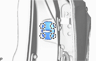
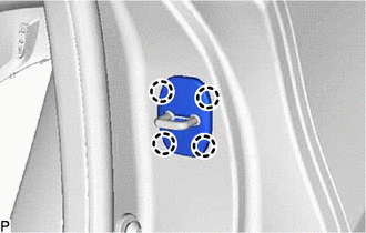
Disengage the 4 claws and remove the front door lock striker cover.
-
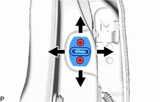
Using a T40 "TORX" socket wrench, slightly loosen the 2 striker mounting screws.
-
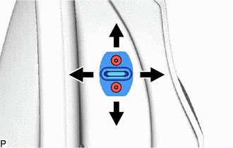
Using a brass bar and a hammer, hit the striker to adjust its position.
-
Using a T40 "TORX" socket wrench, tighten the 2 striker mounting screws after adjustment.
- Torque:
- 23 N*m { 235 kgf*cm, 17 ft.*lbf }
-
Engage the 4 claws to install the front door lock striker cover.
-
-
INSPECT REAR DOOR
-
Check that the clearance measurements of areas a through j are within each standard range.
Standard Clearance Area Measurement Area Measurement a -2.0 to 2.0 mm (-0.0787 to 0.0787 in.) b 2.1 to 6.1 mm (0.0827 to 0.240 in.) c 3.5 to 6.5 mm (0.138 to 0.256 in.) d -0.5 to 2.5 mm (-0.0197 to 0.0984 in.) e 4.7 to 7.7 mm (0.185 to 0.303 in.) f -1.5 to 1.5 mm (-0.0591 to 0.0591 in.) g 2.0 to 5.0 mm (0.0787 to 0.197 in.) h -1.5 to 1.5 mm (-0.0591 to 0.0591 in.) i -1.2 to 1.2 mm (-0.0472 to 0.0472 in.) j 2.3 to 4.7 mm (0.0906 to 0.185 in.) Tech Tips
-
Use the same procedure for the RH side and LH side.
-
The following procedure is for the LH side.
-
Centering bolts are used to install the door hinges to the vehicle body and door. The door cannot be adjusted with the centering bolts installed. Substitute the centering bolts with standard bolts when making adjustments.
-
-
-
ADJUST REAR DOOR
Note
Make sure to turn the ignition switch off when adjusting door lock strikers.
-
Using SST, loosen the 4 hinge bolts on the vehicle body and adjust the door position.
- SST
- 09812-00020
-
Tighten the 4 hinge bolts on the vehicle body after adjustment.
- Torque:
- 32.5 N*m { 331 kgf*cm, 24 ft.*lbf }
-
Loosen the 4 hinge bolts on the door and adjust the door position.
-
Tighten the 4 hinge bolts on the door after adjustment.
- Torque:
- 32.5 N*m { 331 kgf*cm, 24 ft.*lbf }
-
Disengage the 4 claws to remove the rear door lock striker cover.
-
Using a T40 "TORX" socket wrench, slightly loosen the 2 striker mounting screws.
-
Using a brass bar and a hammer, hit the striker to adjust its position.
-
Using a T40 "TORX" socket wrench, tighten the 2 striker mounting screws after adjustment.
- Torque:
- 23 N*m { 235 kgf*cm, 17 ft.*lbf }
-
Engage the 4 claws to install the rear door lock striker cover.
-
-
INSPECT BACK DOOR (w/o Rear No. 2 Seat)
-
Check that the clearance measurements of areas a through g are within each standard range.
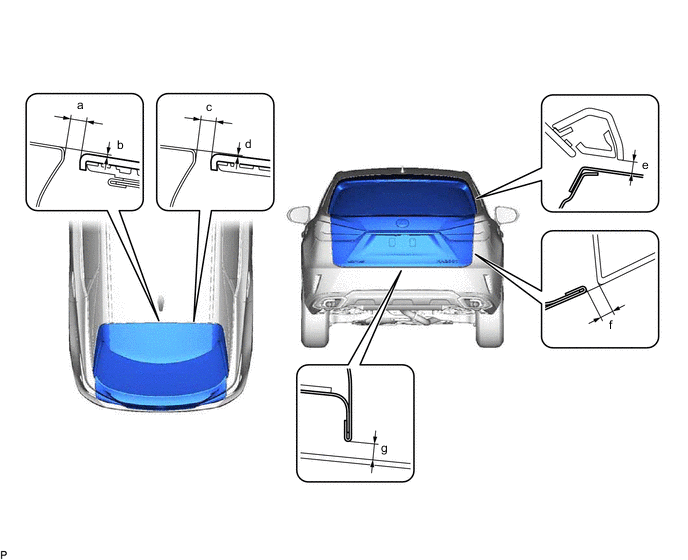
Standard Clearance Area Measurement Area Measurement a 5.95 to 9.95 mm (0.234 to 0.392 in.) b -1.15 to 2.85 mm (-0.0453 to 0.112 in.) c 5.95 to 9.95 mm (0.234 to 0.392 in.) d -1.15 to 2.85 mm (-0.0453 to 0.112 in.) e 3.15 to 7.15 mm (0.124 to 0.281 in.) f 3.85 to 6.85 mm (0.152 to 0.270 in.) g 4.55 to 8.55 mm (0.179 to 0.337 in.) - - Tech Tips
Centering bolts are used to install the door hinges to the vehicle body and door. The door cannot be adjusted with the centering bolts installed. Substitute the centering bolts with standard bolts (with washers) when making adjustments.
-
-
INSPECT BACK DOOR (w/ Rear No. 2 Seat)
-
Check that the clearance measurements of areas a through g are within each standard range.
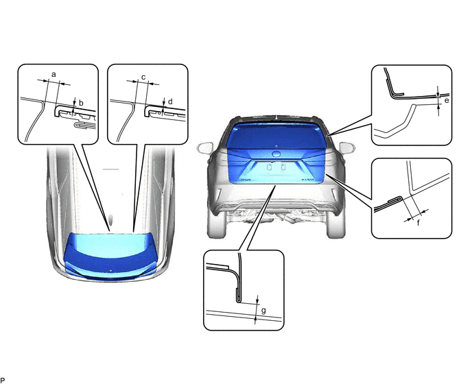
Standard Clearance Area Measurement Area Measurement a 5.95 to 9.95 mm (0.234 to 0.392 in.) b -1.15 to 2.85 mm (-0.0453 to 0.112 in.) c 5.95 to 9.95 mm (0.234 to 0.392 in.) d -1.15 to 2.85 mm (-0.0453 to 0.112 in.) e 2.35 to 6.35 mm (0.0925 to 0.250 in.) f 3.85 to 6.85 mm (0.152 to 0.270 in.) g 3.55 to 7.55 mm (0.140 to 0.297 in.) - - Tech Tips
Centering bolts are used to install the door hinges to the vehicle body and door. The door cannot be adjusted with the centering bolts installed. Substitute the centering bolts with standard bolts (with washers) when making adjustments.
-
-
ADJUST BACK DOOR
-
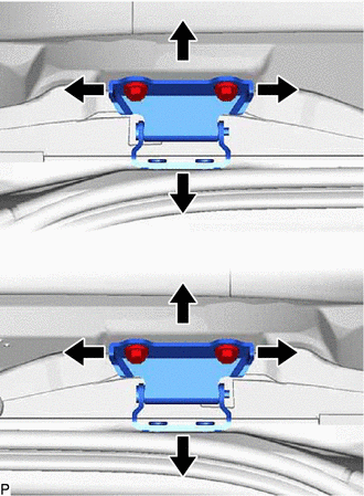
Before adjusting the upper end of the back door up and down or left and right, loosen the 4 hinge bolts on the vehicle body.
-
Tighten the 4 hinge bolts on the vehicle body after adjustment.
- Torque:
- 19.5 N*m { 199 kgf*cm, 14 ft.*lbf }
-
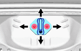
Using a T40 "TORX" socket wrench, slightly loosen the 2 striker mounting screws.
-
Using a brass bar and a hammer, hit the striker to adjust its position.
-
Using a T40 "TORX" socket wrench, tighten the 2 striker mounting screws after adjustment.
- Torque:
- 23 N*m { 235 kgf*cm, 17 ft.*lbf }
-