FIT STANDARD / ADJUSTMENT METHOD ADJUSTMENT
-
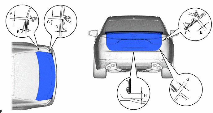
INSPECT HOOD SUB-ASSEMBLY
-
Check that the clearance measurements of areas a through f are within each standard range.
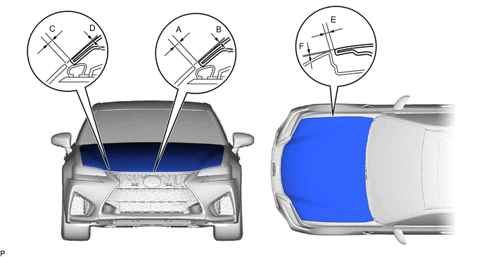
Standard Clearance Area Specified Condition Area Specified Condition A 3.1 to 7.1 mm (0.122 to 0.280 in.) B -1.6 to 2.4 mm (0.060 to 0.094 in.) C 2.3 to 6.3 mm (0.091 to 0.248 in.) D -1.8 to 2.2 mm (-0.071 to 0.087 in.) E 2.5 to 5.5 mm (0.098 to 0.217 in.) F -1.1 to 1.9 mm (-0.043 to 0.075 in.)
Tech Tips
Centering bolts are used to mount the hood hinge to the vehicle body and hood. The hood cannot be adjusted with the centering bolts on. Substitute the centering bolts for standard bolts when making adjustments.
-
-
ADJUST HOOD SUB-ASSEMBLY
-
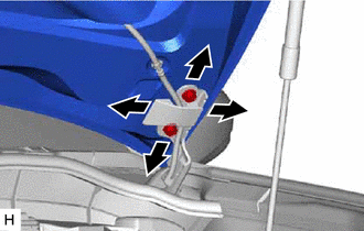
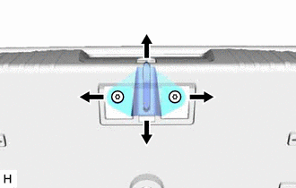
Horizontally and vertically adjust the hood.
-
Loosen the 4 hinge bolts of the hood.
-
Adjust the clearance between the hood and front fender by moving the hood.
-
Tighten the 4 hinge bolts after adjustment.
- Torque:
- 13 N*m { 133 kgf*cm, 9.6 ft.*lbf }
-
-
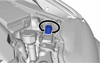
Adjust the height of the front end of the hood using the hood bumper cushions.
-
Adjust the 2 hood bumper cushions so that the heights of the hood and fenders are aligned.
-
-
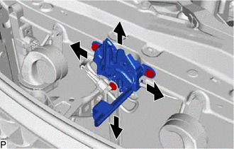
Adjust the hood lock assembly.
-
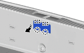
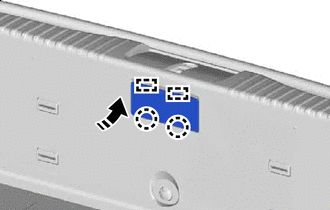
Loosen the 3 bolts.
-
Adjust the hood lock assembly and tighten the 3 bolts.
-
Tighten the 3 bolts after the adjustment.
- Torque:
- 7.5 N*m { 76 kgf*cm, 66 in.*lbf }
-
-
-
INSPECT FRONT DOOR PANEL SUB-ASSEMBLY
-
Check that the clearance measurements of areas A to R are within the standard ranges.
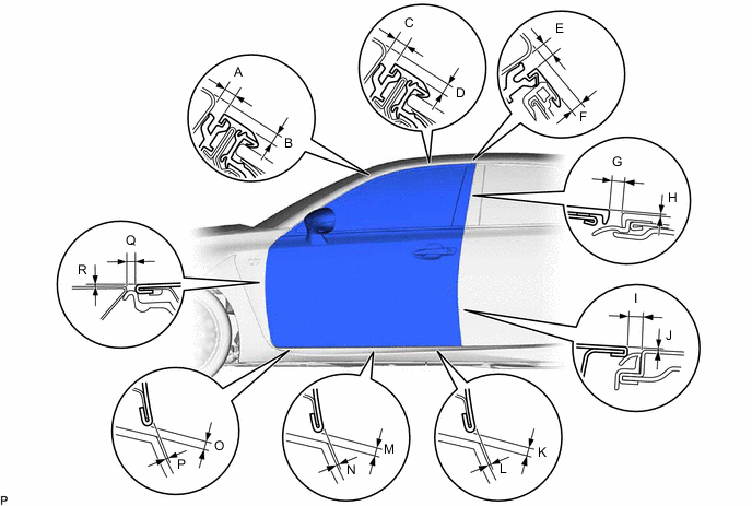
Tech Tips
-
Use the same procedures for both the LH and RH sides.
-
The procedure described below is for the LH side.
-
Centering bolts are used to mount the door hinge to the vehicle body and door. The door cannot be adjusted with the centering bolts on. Substitute the centering bolts for standard bolts when making adjustments.
-
-
ADJUST FRONT DOOR PANEL SUB-ASSEMBLY
-
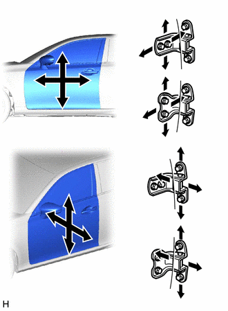
Using SST, loosen the 4 hinge bolts on the body and adjust the door position.
- SST
- 09812-00010
-
Tighten the 4 hinge bolts on the body after the adjustment.
- Torque:
- 26 N*m { 265 kgf*cm, 19 ft.*lbf }
-
Loosen the 4 hinge bolts on the door and adjust the door position.
-
Tighten the 4 hinge bolts on the door after the adjustment.
- Torque:
- 21 N*m { 214 kgf*cm, 15 ft.*lbf }
-
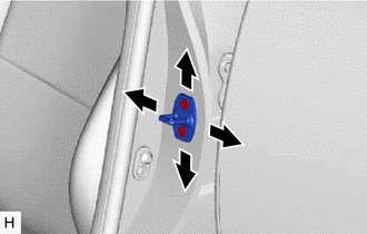
Using a T40 "TORX" socket wrench, slightly loosen the 2 striker mounting screws.
-
Using a brass bar and a hammer, hit the striker to adjust its position.
-
Using a T40 "TORX" socket wrench, tighten the 2 striker mounting screws after adjustment.
- Torque:
- 23 N*m { 235 kgf*cm, 17 ft.*lbf }
-
-
INSPECT REAR DOOR PANEL SUB-ASSEMBLY
-
Check that the clearance measurements of areas A to R are within the standard ranges.
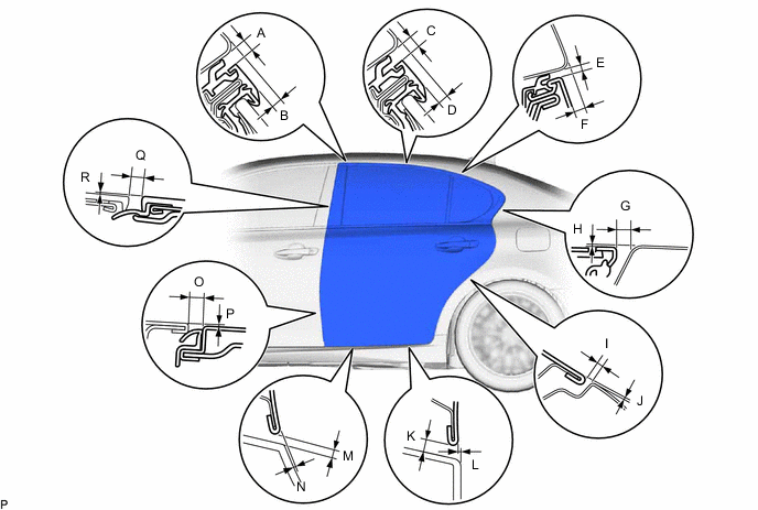
Tech Tips
-
Use the same procedures for both the LH and RH sides.
-
The procedure described below is for the LH side.
-
Centering bolts are used to mount the door hinge to the vehicle body and door. The door cannot be adjusted with the centering bolts on. Substitute the centering bolts for standard bolts when making adjustments.
-
-
ADJUST REAR DOOR PANEL SUB-ASSEMBLY
-
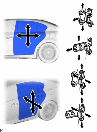
Loosen the 4 hinge bolts on the body and adjust the door position.
-
Tighten the 4 hinge bolts on the body after the adjustment.
- Torque:
- 26 N*m { 265 kgf*cm, 19 ft.*lbf }
-
Loosen the 4 hinge bolts on the door and adjust the door position.
-
Tighten the 4 hinge bolts on the door after the adjustment.
- Torque:
- 21 N*m { 214 kgf*cm, 15 ft.*lbf }
-
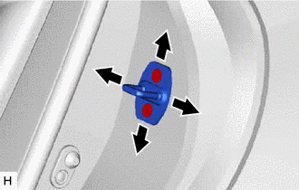
Using a T40 "TORX" socket wrench, slightly loosen the 2 striker mounting screws.
-
Using a brass bar and a hammer, hit the striker to adjust its position.
-
Using a T40 "TORX" socket wrench, tighten the 2 striker mounting screws after adjustment.
- Torque:
- 23 N*m { 235 kgf*cm, 17 ft.*lbf }
-
-
INSPECT LUGGAGE COMPARTMENT DOOR PANEL SUB-ASSEMBLY
-
Check that the clearance measurements of areas A to H are within the standard ranges.
Tech Tips
-
Use the same procedures for both the LH and RH sides.
-
The procedure described below is for the LH side.
-
Centering bolts are used to mount the door hinge to the vehicle body and door. The door cannot be adjusted with the centering bolts on. Substitute the centering bolts for standard bolts when making adjustments.
-
-
ADJUST LUGGAGE COMPARTMENT DOOR PANEL SUB-ASSEMBLY
-
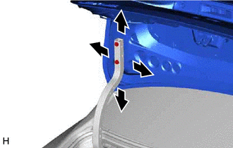
Loosen the 4 hinge bolts on the body and adjust the door position.
-
Tighten the 4 hinge bolts on the body after the adjustment.
- Torque:
- 8.0 N*m { 82 kgf*cm, 71 in.*lbf }
-

Remove in this Direction Disengage the claws and guides to remove the rear luggage room cover as shown in the illustration.
-
Using a T40 "TORX" socket, adjust the striker position by slightly loosening the striker mounting screws and hitting the striker with a plastic hammer.
-
Using a T40 "TORX" socket, tighten the striker mounting screws after the adjustment.
- Torque:
- 23 N*m { 235 kgf*cm, 17 ft.*lbf }
-
Install in this Direction Engage the guides and claws to install the rear luggage room cover as shown in the illustration.
-