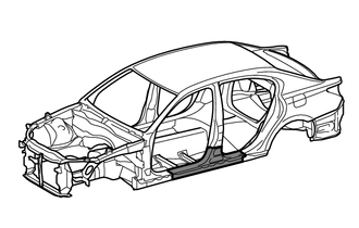
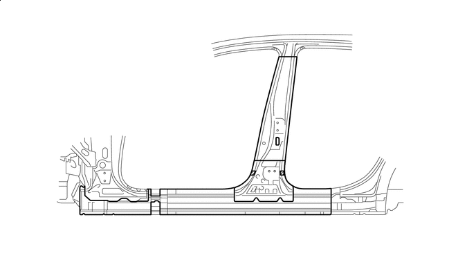
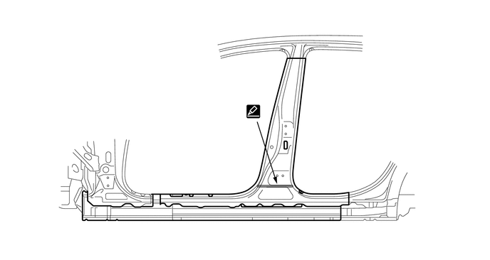
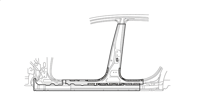
ROCKER PANEL CUT AND JOIN REPLACEMENT SECTIONS
Info Added 2016-03-29 ![]()
-
REMOVAL
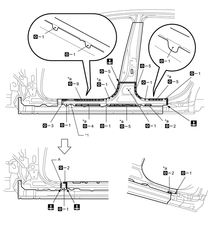
Symbol Meaning 
Remove Weld Points 
Remove Weld Points 
Cut with Disc Sander etc. 
Cut and Join Location 
Cut Location for Supply Parts
-
Do not butt weld or heat repair because the heat decreases the strength of areas where ultra high strength steel is used. (See the introduction)
-
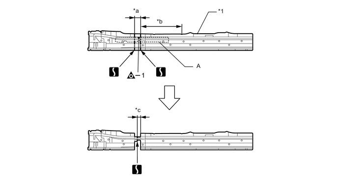
Reuse A, as the area of the outer panel that is cut and joined is to the front of the supplied part cut position.
Tech Tips
Carefully cut the rocker panel sub-assembly outer so as not to damage B.
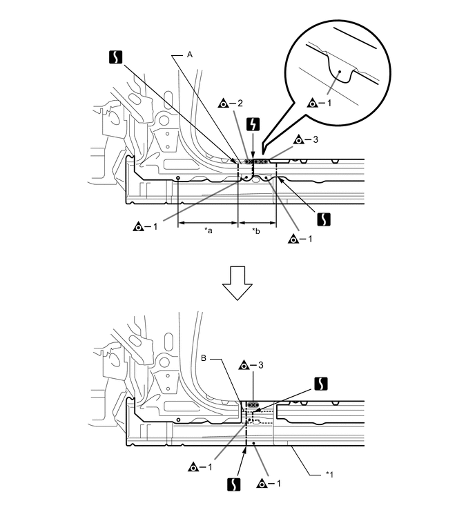
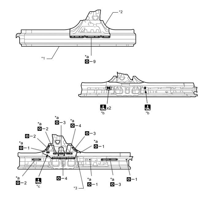
*1 ROCKER PANEL SUB-ASSEMBLY OUTER - - *a 240 mm (9.45 in.) *b 160 mm (6.30 in.) 
Laser Screw Welding - - -
Roughly cut open the panel so that the adhesive can be reached. Cut through the adhesive with a cut chisel to remove the panel.
Tech Tips
In cases where the adhesive cannot be removed with a cut chisel, heat the adhesive with an industrial heater gun or gas burner taking care not to cause panel deformation by overheating.
-
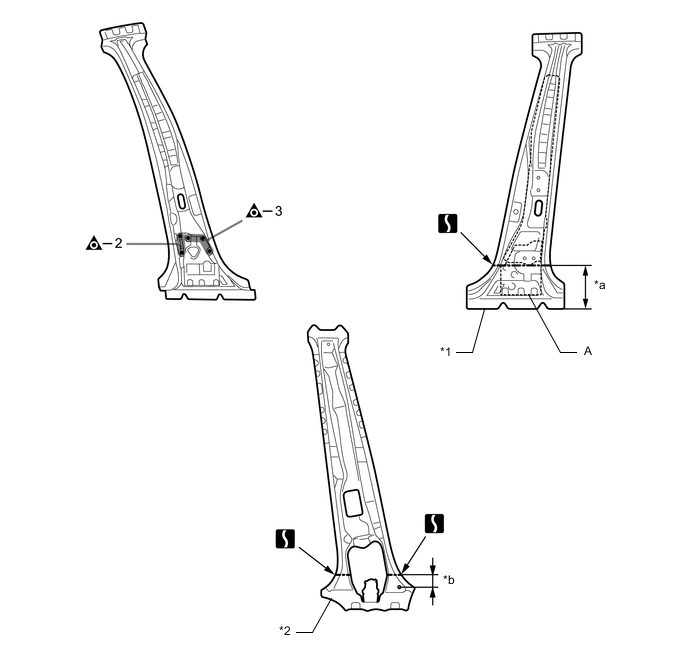
Carefully cut the center body pillar reinforcement sub-assembly so not to damage A.
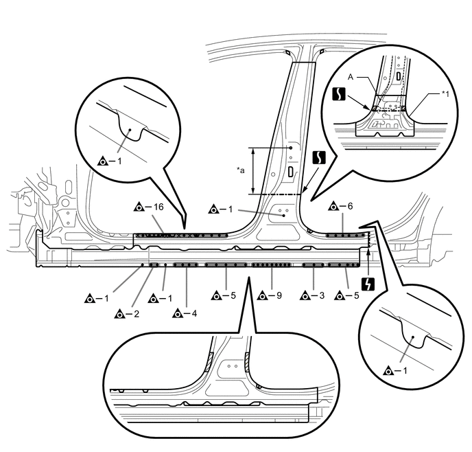
*1 CENTER BODY PILLAR REINFORCEMENT SUB-ASSEMBLY - - *a 265 mm (10.43 in.) - - 
Adhesive Laser Screw Welding 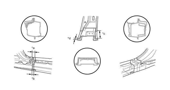
*a 35 mm (1.38 in.) *b 25 mm (0.98 in.) *c 100 mm (3.94 in.) *d 20 mm (0.79 in.) 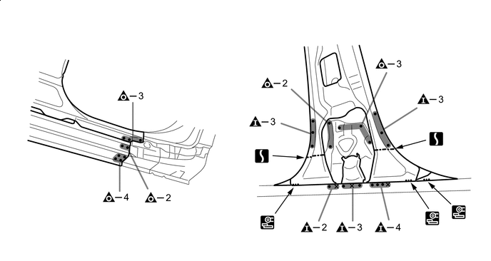
Laser Screw Welding - -
-
-
INSTALLATION
Symbol Meaning Remove Weld Points 
Spot Weld 
Plug Weld 
Plug Weld Cut and Join Location 
Fillet Weld 
Butt Weld 
Body Sealer
-
Inspect the fitting of the related parts around the new parts before welding. This affects the appearance of the finish.
-
Temporarily install the new parts and measure each part of the new parts in accordance with the body dimension diagram. (See the body dimensions)
-
If the entire supply part is not needed, remove the part of the supply part that is needed.
Tech Tips
Carefully cut the rocker panel sub-assembly outer so not to damage A.
*1 ROCKER PANEL SUB-ASSEMBLY OUTER - - *a 60 mm (2.36 in.) *b 430 mm (16.93 in.) *c 35 mm (1.38 in.) - - -
If the entire supply part is not needed, remove the part of the supply part that is needed.
Tech Tips
Carefully cut the center body pillar reinforcement sub-assembly so not to damage A.
*1 CENTER BODY PILLAR REINFORCEMENT SUB-ASSEMBLY *2 CENTER BODY PILLAR SUB-ASSEMBLY INNER *a 175 mm (6.89 in.) *b 50 mm (1.97 in.) -
Apply adhesive (3MTMAutomixTMPanel Bonding Adhesive #8115).
Tech Tips
-
Apply a light coat of adhesive around the plug welding points.
-
Apply enough adhesive to the panels.
Adhesive - - -
-
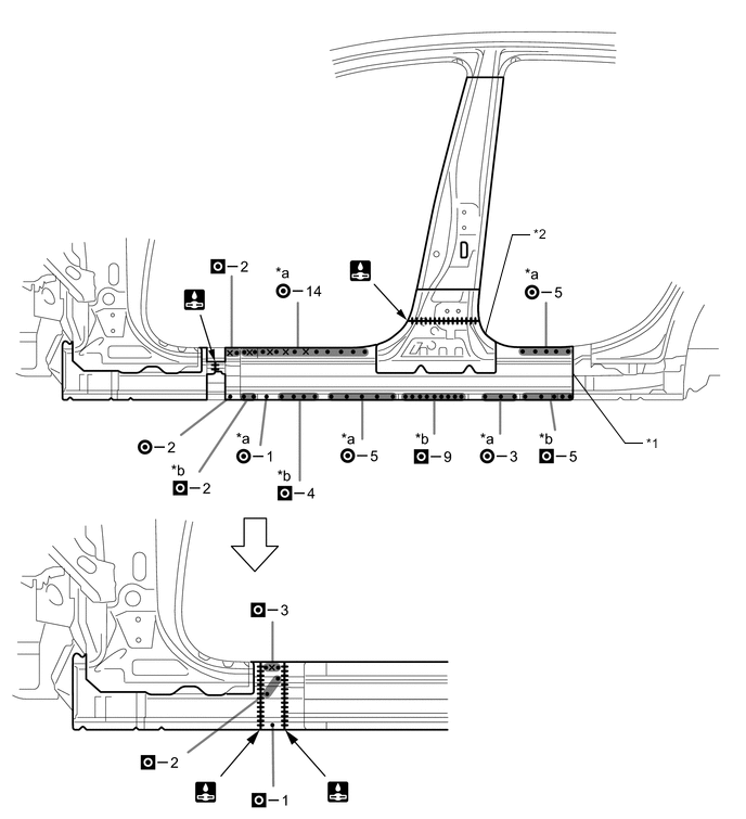
Before temporarily installing the new parts, weld the rocker panel sub-assembly outer, center body pillar reinforcement sub-assembly and center body pillar sub-assembly inner with the standard number of welding points.
*1 ROCKER PANEL SUB-ASSEMBLY OUTER *2 CENTER BODY PILLAR REINFORCEMENT SUB-ASSEMBLY *3 CENTER BODY PILLAR SUB-ASSEMBLY INNER - - *a Ultra High Strength Steel Welding Point *b 10 mm (0.39 in.) *c 20 mm (0.79 in.) - - Laser Screw Welding - -
-
When welding 2 panels together including 980 MPa ultra high strength steel.
*a: Plug weld Plug diameter 10 mm (0.39 in.) Wire type AWS A5.18 ER70S-3 Shield gas Metal active gas Note
Be sure to use Metal active gas (Ar 80% + CO220%) as the shield gas when plug welding.Sufficient weld strength cannot be assured when using 100% CO2shield gas.
Follow the welding conditions below when welding ultra high strength steel to assure sufficient weld strength. (When repairing this model)
-
-
Apply adhesive (3MTMAutomixTMPanel Bonding Adhesive #8115).
Tech Tips
-
Apply a light coat of adhesive around the plug welding points.
-
Apply enough adhesive to the panels.
Adhesive - - -
-
Weld the rocker panel sub-assembly outer, center body pillar reinforcement sub-assembly and center body pillar sub-assembly inner to the vehicle side.
*1 ROCKER PANEL SUB-ASSEMBLY OUTER *2 CENTER BODY PILLAR REINFORCEMENT SUB-ASSEMBLY *a Ultra High Strength Steel Welding Point *b Ultra High Strength Steel Welding Point Laser Screw Welding - -
-
When welding 2 panels together including 980 MPa ultra high strength steel.
*a: Spot weld Pressure 2940 N (300 kgf, 661 lbf) Weld current 10000 A Weld time 18 Cyc.(0.30 Sec.) *b: Plug weld Plug diameter 10 mm (0.39 in.) Wire type AWS A5.18 ER70S-3 Shield gas Metal active gas Note
Be sure to use Metal active gas (Ar 80% + CO220%) as the shield gas when plug welding.Sufficient weld strength cannot be assured when using 100% CO2shield gas.
Follow the welding conditions below when welding ultra high strength steel to assure sufficient weld strength. (When repairing this model)
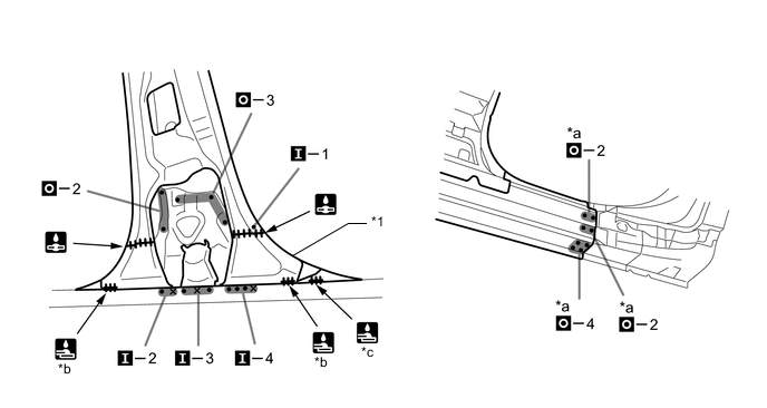
*1 CENTER BODY PILLAR SUB-ASSEMBLY INNER - - *a Ultra High Strength Steel Welding Point *b 20 mm (0.79 in.) *c 15 mm (0.59 in.) - - Laser Screw Welding - -
-
When welding 2 panels together including 980 MPa ultra high strength steel.
*a: Plug weld Plug diameter 10 mm (0.39 in.) Wire type AWS A5.18 ER70S-3 Shield gas Metal active gas Note
Be sure to use Metal active gas (Ar 80% + CO220%) as the shield gas when plug welding.Sufficient weld strength cannot be assured when using 100% CO2shield gas.
Follow the welding conditions below when welding ultra high strength steel to assure sufficient weld strength. (When repairing this model)
-
-
Before installing a new part, apply body sealer.
Tech Tips
Apply body sealer in an even, continuous bead.
-
Apply adhesive (3MTMAutomixTMPanel Bonding Adhesive #8115).
Tech Tips
-
Apply a light coat of adhesive around the plug welding points.
-
Apply enough adhesive to the panels.
Adhesive - - -
-
Weld the center body pillar outer and A to the vehicle side.
*1 CENTER BODY PILLAR OUTER - - *a Ultra High Strength Steel Welding Point - - Laser Screw Welding - -
-
When welding more than 3 panels together including 980 MPa ultra high strength steel. (When plug welding a third panel to 2 panels which are welded under the conditions described above.)
*a: Plug weld Plug diameter Same as the standard method (See the introduction) Wire type AWS A5.18 ER70S-3 Shield gas Metal active gas Note
Be sure to use Metal active gas (Ar 80% + CO220%) as the shield gas when plug welding.Sufficient weld strength cannot be assured when using 100% CO2shield gas.
Follow the welding conditions below when welding ultra high strength steel to assure sufficient weld strength. (When repairing this model)
-
-
After welding, apply the foamed sealing material to the corresponding parts. (See the painting/coating)
-
After welding, apply body sealer to the corresponding parts. (See the painting/coating)
-
After applying the top coat, apply anti-rust agent to the internal panel portion of the closed section structural weld points.
-