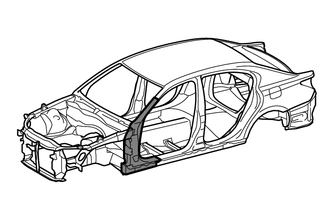
FRONT BODY PILLAR CUT AND JOIN REPLACEMENT SECTIONS
Info Added 2016-03-29 ![]()
-
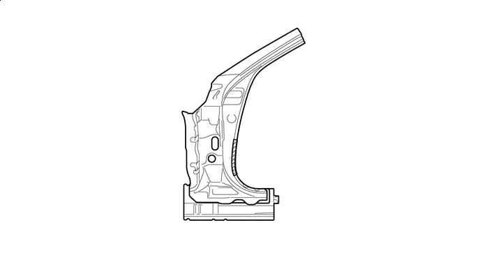
With the cowl top side upper panel assembly and front body pillar lower gusset assembly removed.
-
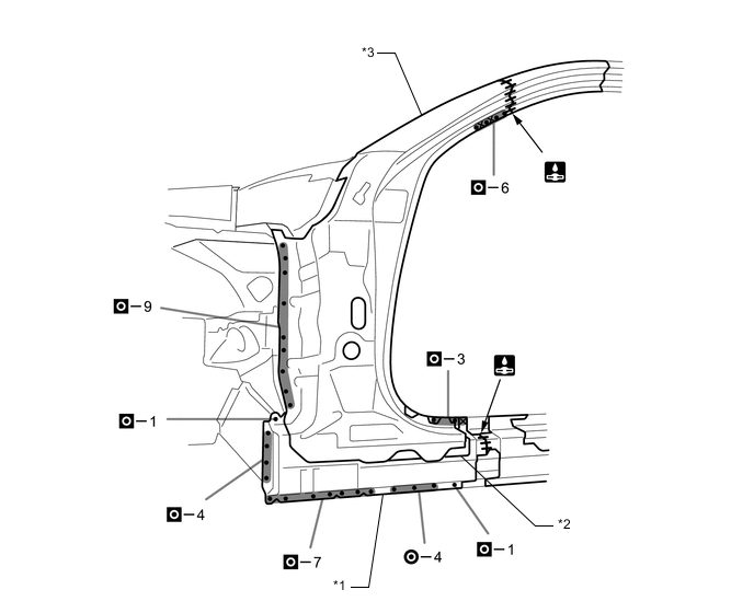
REMOVAL
Symbol Meaning 
Remove Weld Points 
Remove Weld Points 
Remove Weld Points 
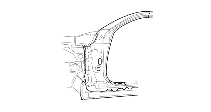
Cut with Disc Sander etc. 
Cut and Join Location 
Cut Location for Supply Parts
-
Reuse A, as the area of the outer panel that is cut and joined is to the rear of the supplied part cut position.
Tech Tips
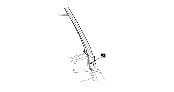
Carefully cut the rocker panel sub-assembly outer so as not to damage B.
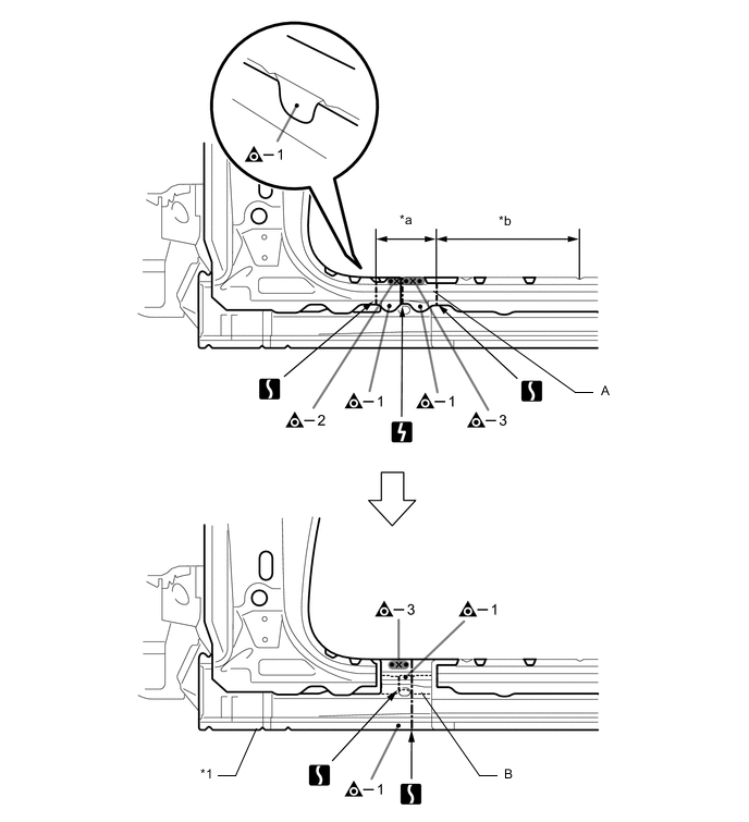
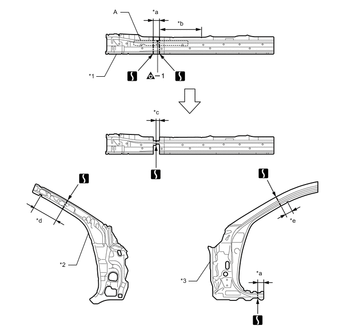
*1 ROCKER PANEL SUB-ASSEMBLY OUTER - - *a 160 mm (6.30 in.) *b 365 mm (14.37 in.) 
Laser Screw Welding - - -
Roughly cut open the panel so that the adhesive can be reached. Cut through the adhesive with a cut chisel to remove the panel.
Tech Tips
In cases where the adhesive cannot be removed with a cut chisel, heat the adhesive with an industrial heater gun or gas burner taking care not to cause panel deformation by overheating.
-
Be careful when cutting as foamed sealing material is located near the cutting position.

Adhesive 
Foamed Sealing Material Laser Screw Welding - - 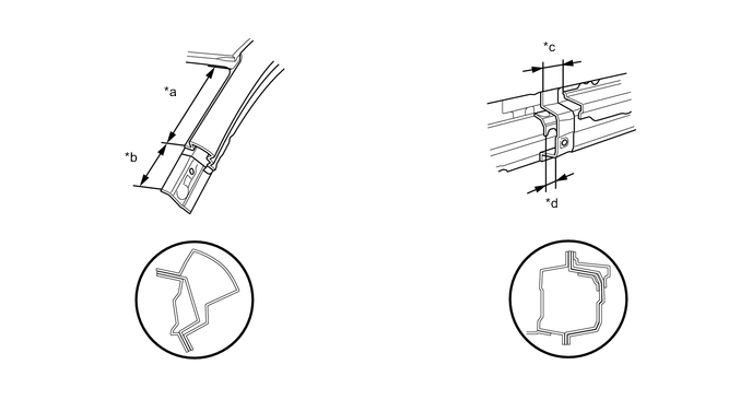
*a 230 mm (9.06 in.) *b 110 mm (4.33 in.) *c 65 mm (2.56 in.) *d 35 mm (1.38 in.) 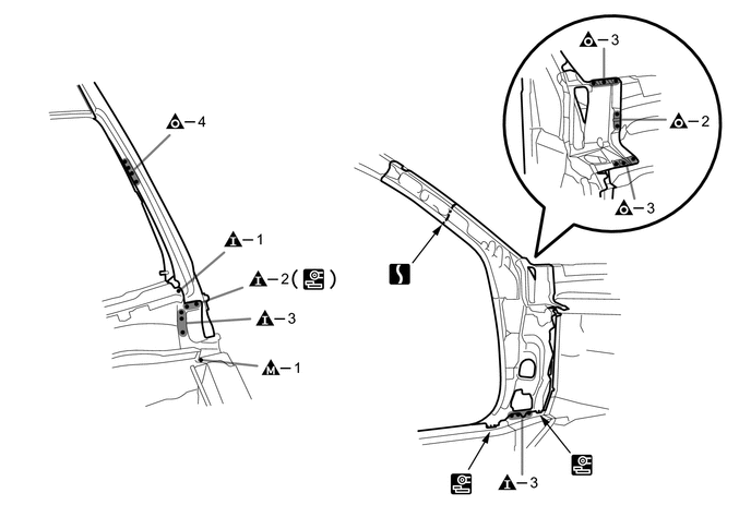
-
When replace only the outer panel, please cut off a necessary range depending on a damage range.
-
Carefully cut the outer panel so not to damage the reinforcement.
-
Make sure that butt welding does not heat-affect the reinforcement when welding the outer panel.
-
-
-
INSTALLATION
Symbol Meaning Remove Weld Points 
Spot Weld 
Plug Weld 
Plug Weld 
Plug Weld Cut and Join Location 
Fillet Weld 
Butt Weld 
Body Sealer
-
Inspect the fitting of the related parts around the new parts before welding. This affects the appearance of the finish.
-
Temporarily install the new parts and measure each part of the new parts in accordance with the body dimension diagram. (See the body dimensions)
-
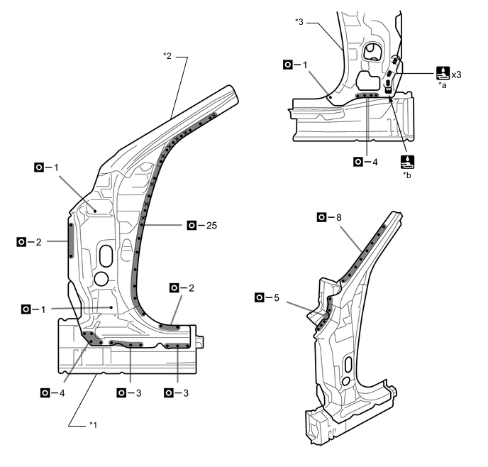
If the entire supply part is not needed, remove the part of the supply part that is needed.
Tech Tips
Carefully cut the rocker panel sub-assembly outer so as not to damage A.
*1 ROCKER PANEL SUB-ASSEMBLY OUTER *2 FRONT BODY PILLAR SUB-ASSEMBLY INNER *3 FRONT BODY PILLAR OUTER - - *a 60 mm (2.36 in.) *b 430 mm (16.93 in.) *c 35 mm (1.38 in.) *d 190 mm (7.48 in.) *e 80 mm (3.15 in.) - - -
Apply adhesive (3MTMAutomixTMPanel Bonding Adhesive #8115).
Tech Tips
-
Apply a light coat of adhesive around the plug welding points.
-
Apply enough adhesive to the panels.
Adhesive - - -
-
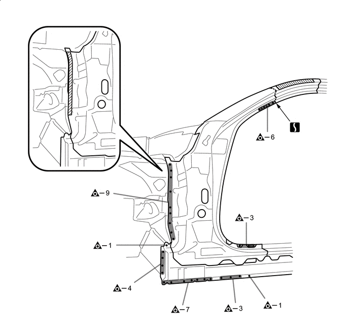
Before temporarily installing the new parts, weld the rocker panel sub-assembly outer, front body pillar reinforce sub-assembly upper and front body pillar sub-assembly inner with the standard number of welding points.
*1 ROCKER PANEL SUB-ASSEMBLY OUTER *2 FRONT BODY PILLAR REINFORCE SUB-ASSEMBLY UPPER *3 FRONT BODY PILLAR SUB-ASSEMBLY INNER - - *a 7 mm (0.28 in.) *b 15 mm (0.59 in.) Laser Screw Welding - - -
Apply adhesive (3MTMAutomixTMPanel Bonding Adhesive #8115).
Tech Tips
-
Apply a light coat of adhesive around the plug welding points.
-
Apply enough adhesive to the panels.
Adhesive - - -
-
Before temporarily installing the new parts, weld the rocker panel sub-assembly outer, front body pillar reinforce sub-assembly upper, front body pillar sub-assembly inner and front body pillar outer with the standard number of welding points.
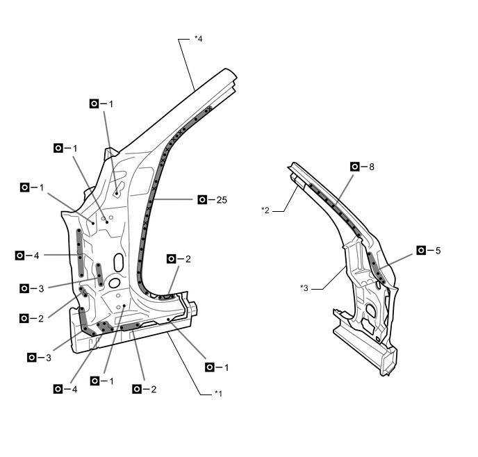
*1 ROCKER PANEL SUB-ASSEMBLY OUTER *2 FRONT BODY PILLAR REINFORCE SUB-ASSEMBLY UPPER *3 FRONT BODY PILLAR SUB-ASSEMBLY INNER *4 FRONT BODY PILLAR OUTER Laser Screw Welding - - -
Before installing a new part, apply body sealer.
Tech Tips
Apply body sealer in an even, continuous bead.
-
Apply adhesive (3MTMAutomixTMPanel Bonding Adhesive #8115).
Tech Tips
-
Apply a light coat of adhesive around the plug welding points.
-
Apply enough adhesive to the panels.
Adhesive - - -
-
Weld the rocker panel sub-assembly outer, front body pillar reinforce sub-assembly upper, front body pillar sub-assembly inner and front body pillar outer to the vehicle side.
*1 ROCKER PANEL SUB-ASSEMBLY OUTER *2 FRONT BODY PILLAR REINFORCE SUB-ASSEMBLY UPPER *3 FRONT BODY PILLAR OUTER - - Laser Screw Welding - - 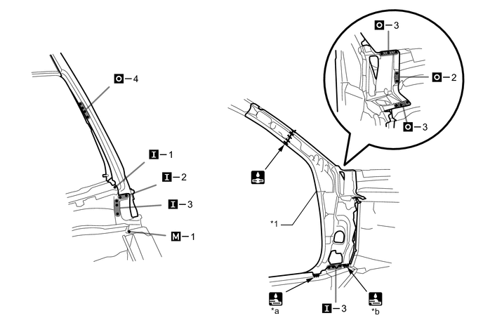
*1 FRONT BODY PILLAR SUB-ASSEMBLY INNER - - *a 19 mm (0.75 in.) *b 15 mm (0.59 in.) -
Weld the A and B to the vehicle side.
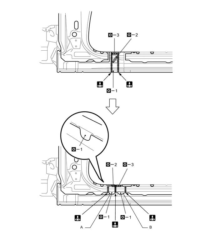
Laser Screw Welding - - -
After welding, apply the foamed sealing material to the corresponding parts. (See the painting/coating)
-
After welding, apply body sealer to the corresponding parts. (See the painting/coating)
-
After applying the top coat, apply anti-rust agent to the internal panel portion of the closed section structural weld points.
-