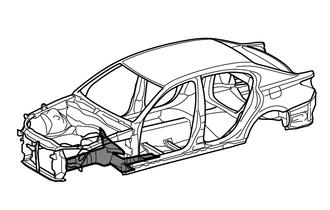
FRONT SIDE MEMBER ASSEMBLY REPLACEMENT
Info Added 2016-03-29 ![]()
-
With the front fender apron assembly removed.
-
REMOVAL
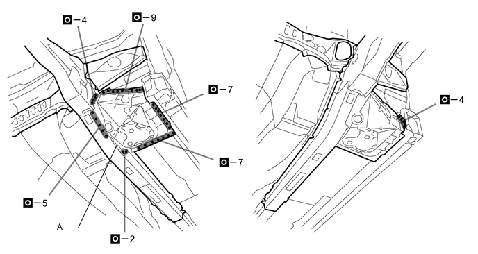
Symbol Meaning 
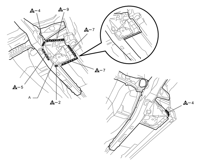
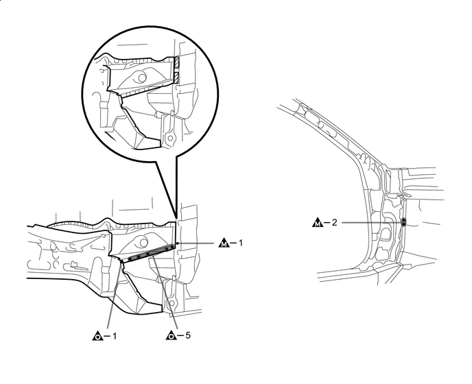
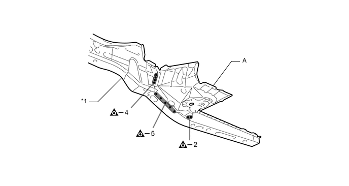
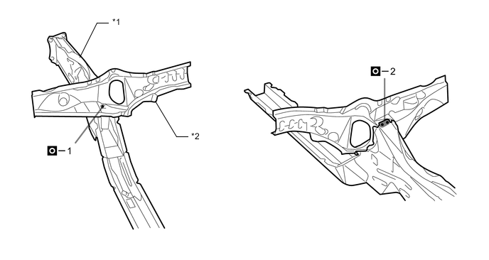
Remove Weld Points 
Remove Weld Points 
Cut and Join Location
-
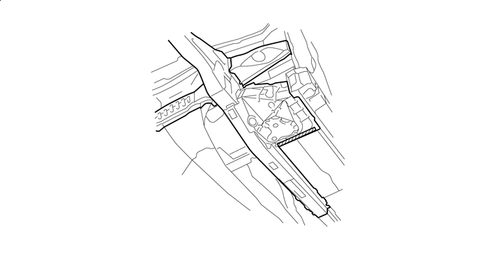
Remove the A.
-
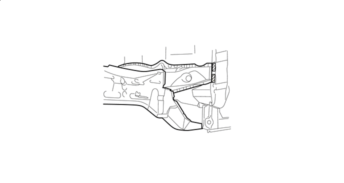
Roughly cut open the panel so that the adhesive can be reached. Cut through the adhesive with a cut chisel to remove the panel.
Tech Tips
In cases where the adhesive cannot be removed with a cut chisel, heat the adhesive with an industrial heater gun or gas burner taking care not to cause panel deformation by overheating.

Adhesive - - -
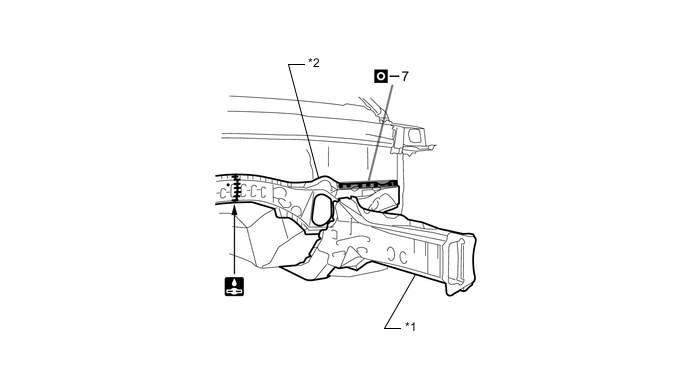
Remove the front side member sub-assembly and floor crossmember sub-assembly No.3.
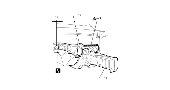
*1 FRONT SIDE MEMBER SUB-ASSEMBLY *2 FLOOR CROSSMEMBER SUB-ASSEMBLY NO.3 *a 35 mm (1.38 in.) - - 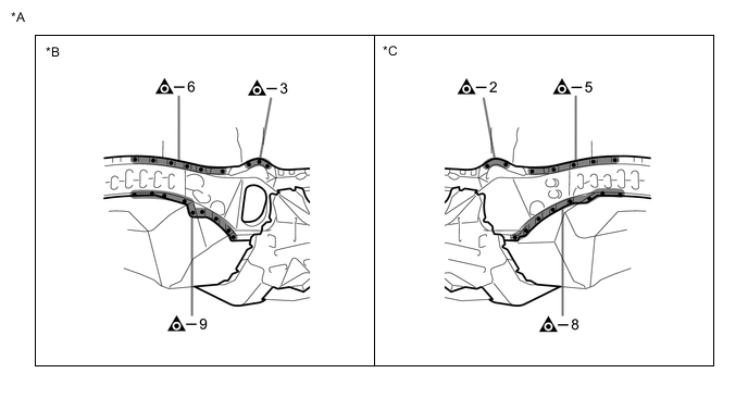
*A for LHD *B LH Side *C RH Side - - 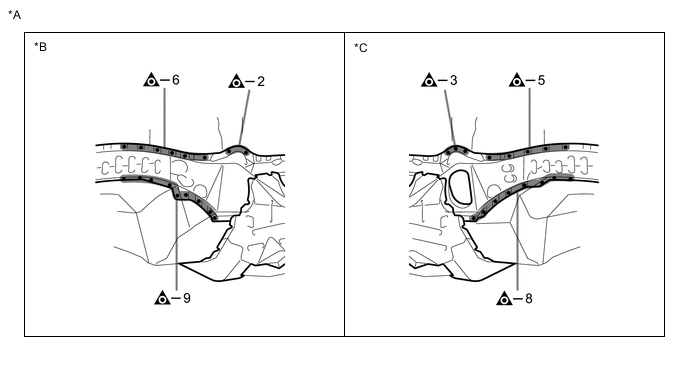
*A for RHD *B LH Side *C RH Side - - -
Roughly cut open the panel so that the adhesive can be reached. Cut through the adhesive with a cut chisel to remove the panel.
Tech Tips
In cases where the adhesive cannot be removed with a cut chisel, heat the adhesive with an industrial heater gun or gas burner taking care not to cause panel deformation by overheating.
Adhesive - - 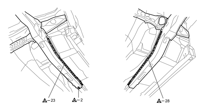
-
-
INSTALLATION
Symbol Meaning Remove Weld Points 
Plug Weld 
Plug Weld Cut and Join Location 
Butt Weld
-
Temporarily install the new parts and measure each part of the new parts in accordance with the body dimension diagram. (See the body dimensions)
-
Make sure to attach correctly in accordance with the body dimension diagram as this part affects the front wheel alignment.
-
If the entire supply part is not needed, remove the part of the supply part that is needed.
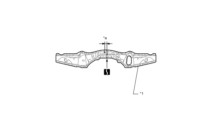
*1 FLOOR CROSSMEMBER SUB-ASSEMBLY NO.3 - - *a 35 mm (1.38 in.) - - -
Remove A from the new parts.
*1 FRONT SIDE MEMBER SUB-ASSEMBLY - - -
Before temporarily installing the new parts, weld the front side member sub-assembly and floor crossmember sub-assembly No.3 with the standard number of welding points.
*1 FRONT SIDE MEMBER SUB-ASSEMBLY *2 FLOOR CROSSMEMBER SUB-ASSEMBLY NO.3 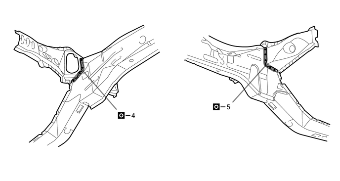
-
Apply adhesive (3MTMAutomixTMPanel Bonding Adhesive #8115).
Tech Tips
-
Apply a light coat of adhesive around the plug welding points.
-
Apply enough adhesive to the panels.
Adhesive - - -
-
Weld the front side member sub-assembly and floor crossmember sub-assembly No.3 to the vehicle side.
*1 FRONT SIDE MEMBER SUB-ASSEMBLY *2 FLOOR CROSSMEMBER SUB-ASSEMBLY NO.3 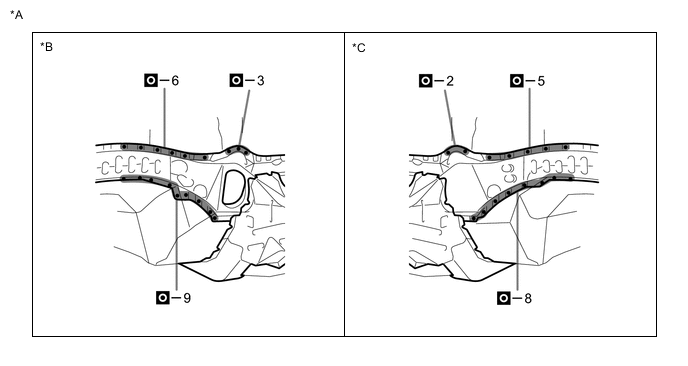
*A for LHD *B LH Side *C RH Side - - 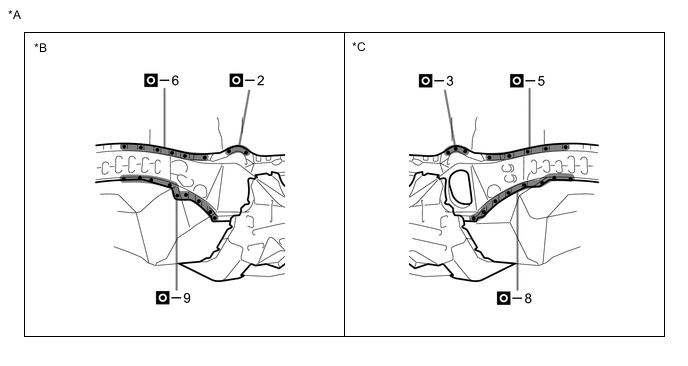
*A for RHD *B LH Side *C RH Side - - 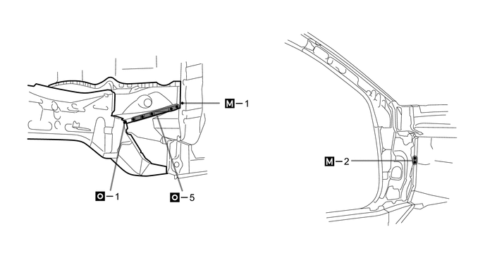

-
Apply adhesive (3MTMAutomixTMPanel Bonding Adhesive #8115).
Tech Tips
-
Apply a light coat of adhesive around the plug welding points.
-
Apply enough adhesive to the panels.
Adhesive - - -
-
Weld the A to the vehicle side.
-
After welding, apply body sealer and undercoating to the corresponding parts. (See the painting/coating)
-
After applying the top coat, apply anti-rust agent to the internal panel portion of the closed section structural weld points.
-