SFI SYSTEM DETAILS
-
FUNCTION OF MAIN COMPONENTS
-
The main components of the engine control system are as follows:
Component Outline Quantity Function ECM 32-bit CPU 1 The ECM optimally controls the SFI, ESA and ISC to suit the operating conditions of the engine in accordance with the signals provided by the sensors. Intake Mass Air Flow Meter Sub assembly Hot-wire Type 1 This sensor has a built-in hot-wire to directly detect the intake air mass. Intake Air Temperature Sensor Thermistor Type 1 This sensor detects the intake air temperature by means of an internal thermistor. Engine Coolant Temperature Sensor Thermistor Type 1 This sensor detects the engine coolant temperature by means of an internal thermistor. Fuel Pressure Sensor Semiconductor Type 1 The sensor senses the fuel pressure in the delivery pipe. Crankshaft Position Sensor [Rotor Teeth] Pick-up Coil Type [36 - 2] 1 This sensor detects the engine speed and performs cylinder identification. Camshaft Position Sensor for Intake [Rotor Teeth] Magnetic Resistance Element (MRE) Type [3] 2 (1 each bank)
-
This sensor is used to detect the camshaft position.
-
This sensor performs cylinder identification.
Camshaft Position Sensor for Exhaust [Rotor Teeth] Magnetic Resistance Element (MRE) Type [3] 2 (1 each bank)
-
This sensor is used to detect the camshaft position.
-
This sensor performs cylinder identification.
Accelerator Pedal Position Sensor Linear (Non-contact) Type 1 This sensor detects the amount of pedal effort applied to the accelerator pedal. Throttle Position Sensor Linear (Non-contact) Type 1 This sensor detects the throttle valve opening angle. Knock Control Sensor 1 and 2 Built-in Piezoelectric Type (Non-resonant Type/Flat Type) 2 (1 each bank) This sensor detects an occurrence of the engine knocking indirectly from the vibration of the cylinder block caused by the occurrence of engine knocking. Air Fuel Ratio Sensor (Bank 1, Sensor 1) (Bank 2, Sensor 1) Heated Type (Planar Type) 2 (1 each bank) As with the oxygen sensor, this sensor detects the oxygen concentration in the exhaust emissions. However, it detects the oxygen concentration in the exhaust emissions linearly. Oxygen Sensor (Bank 1, Sensor 2) (Bank 2, Sensor 2) Heated Type (Cup Type) 2 (1 each bank) This sensor detects the oxygen concentration in the exhaust emissions by measuring the electromotive force which is generated in the sensor itself. Fuel Injector Assembly High Pressure Slit Nozzle Type 6 This injector contains a high-pressure electro-magnetically operated nozzle to inject fuel directly into the cylinder. Electronic Driver Unit (EDU) Built-in DC/DC Converter 1 The EDU converts the signals from the ECM into high-voltage, high-amperage current in order to drive the direct injection injectors. -
-
-
SYSTEM CONTROL
-
The engine control system has the following features. The ECM controls these systems:
System Outline Direct Injection 4-stroke Gasoline Engine Sequential Multiport Fuel Injection (D-4 SFI)
-
This is an L-type SFI system. It directly detects the intake air mass with a hot wire type intake mass air flow meter sub-assembly.
-
Unlike a conventional gasoline engine, the D-4 SFI system precisely controls both the injection timing and injection volume.
-
Based on signals from various sensors, the ECM controls the injection volume and timing of fuel injector assembly in accordance with the engine speed and engine load in order to optimize combustion conditions.
Electronic Spark Advance (ESA)
-
Ignition timing is determined by the ECM based on signals from various sensors. The ECM corrects ignition timing in response to engine knocking.
-
This system selects the optimal ignition timing in accordance with the signals received from the sensors and sends (IGT) ignition signals to the igniters.
Electronic Throttle Control System-intelligent (ETCS-i) Optimally controls the opening angle of the throttle valve in accordance with the accelerator pedal input and the engine and vehicle conditions. Dual Variable Valve Timing-intelligent (Dual VVT-i) Controls the intake and exhaust camshafts to an optimal valve timing in accordance with engine operating conditions. Acoustic Control Induction System (ACIS) The intake air passages are switched based on engine speed and throttle valve opening angle to provide high performance in all engine speed ranges. Electronic Swirl Control Valve (SCV) System Optimally controls the air currents (to assist mixture stratification) in the combustion chamber by closing one of the independent intake ports in accordance with the engine coolant temperature and engine condition, in order to stabilize the combustion and enhance performance. Fuel Pump Control For High-pressure Pump Regulates the fuel pressure within a range of 4 to 13 MPa in accordance with driving conditions. For Low-pressure Pump
-
Based on signals from the ECM, the fuel pump control ECU controls the fuel pump.
-
The fuel pump is stopped when a Supplemental Restraint System (SRS) airbag is deployed.
Air Conditioning Cut-off Control By turning the air conditioning compressor on or off in accordance with the engine operating conditions, driveability is maintained. Cooling Fan Control The cooling fan ECU steplessly controls the speed of the fans in accordance with the engine coolant temperature, vehicle speed, engine speed, and air conditioning operating conditions. As a result, the cooling performance is improved. Starter Control (Cranking Hold Function) Once the engine switch (push start switch) is pushed, this control operates the starter until the engine starts. Air Fuel Ratio Sensor and Oxygen Sensor Heater Control Maintains the temperature of the air fuel ratio sensors or oxygen sensors at an appropriate level to increase the ability of the sensors to accurately detect the oxygen concentration. Engine Immobiliser Prohibits fuel delivery and ignition if an attempt is made to start the engine with an invalid key. Brake Override System Restricts the driving torque when both the accelerator and brake pedals are depressed. (For the Activation Conditions and Inspection Method, refer to the Repair Manual.) Fail-safe When the ECM detects a malfunction, it stops or controls the engine in accordance with the data already stored in memory. Diagnosis When the ECM detects a malfunction, it records the malfunction and information that relates to the fault. -
-
-
FUNCTION
-
Direct Injection 4-stroke Gasoline Engine Sequential Multiport Fuel Injection (D-4 SFI) System
-
The D-4 SFI system directly detects the intake air mass with a hot wire type intake mass air flow meter sub-assembly.
-
Unlike a conventional gasoline engine, the D-4 SFI system precisely controls both the injection timing (relative to the intake or compression stroke) and injection volume. In order to correctly inject the fuel directly into the cylinders on a gasoline engine that uses direct injection (D-4), the injection timing must be precisely controlled. This control of injection timing for a direct injection engine has a similar importance to ignition timing control for an engine with conventional intake port type fuel injection. There is a significant difference between direct injection and synchronous injection that occurs on a conventional port injected engine.
-
Based on the signals from various sensors, the ECM controls the injection volume and injection timing to suit the engine speed and the engine load, in order to achieve an optimal state of combustion.
-
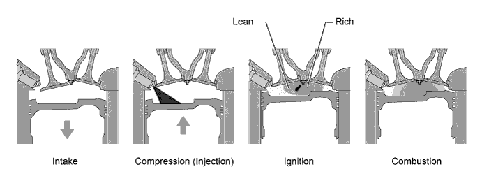
To promote the warm-up of the catalyst following a cold start, this system effects lean-burn mixture control through use of a weak stratified combustion process.
-
Weak Stratified Combustion: This process involves injecting fuel during the latter half of the compression stroke following a cold engine start. This produces a weak stratified combustion process. This process allows the use of a hotter burning lean mixture (approximately 16.0:1) when cold. The ability to run the engine on a leaner mixture when cold is due to the injection of the fuel into the compression heated air in the cylinder (injection during latter stages of the compression stroke). This raises the combustion temperature, promotes rapid warm-up of the catalysts, and significantly reduces exhaust emissions.
-
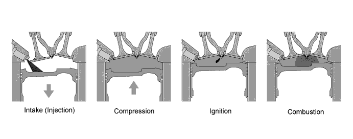
Homogeneous Combustion: By injecting fuel during the first half of the intake stroke, the engine creates a more homogeneous air-fuel mixture. In addition, by utilizing the heat of evaporation of the injected fuel to cool the compressed air, the engine has increased its charging efficiency and produces a higher power output.
-
-
Dual VVT-i System
-
The Dual Variable Valve Timing-intelligent (VVT-i) system is designed to control the intake and exhaust camshaft within a range of 40° and 35° respectively (of crankshaft angle) to provide valve timing that is optimally suited to the engine operating conditions. This improves torque in all the speed ranges as well as increasing fuel economy, and reducing exhaust emissions.
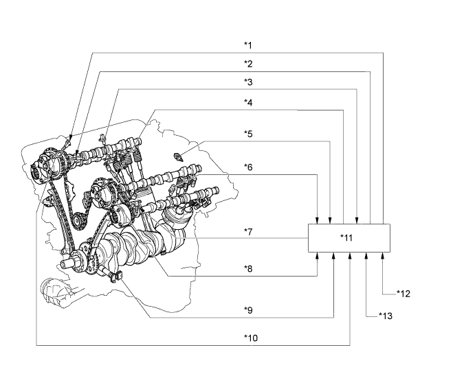
Text in Illustration *1 Camshaft Timing Oil Control Valve Assembly (Exhaust RH) *2 Camshaft Timing Oil Control Valve Assembly (Intake RH) *3 Camshaft Position Sensor (Exhaust RH) *4 Camshaft Timing Oil Control Valve Assembly (Intake LH) *5 Engine Coolant Temperature Sensor *6 Camshaft Position Sensor (Exhaust LH) *7 Camshaft Timing Oil Control Valve Assembly (Exhaust LH) *8 Camshaft Position Sensor (Intake LH) *9 Crankshaft Position Sensor *10 Camshaft Position Sensor (Intake RH) *11 ECM *12 Intake Mass Air Flow Meter Sub-assembly *13 Throttle Position Sensor - - 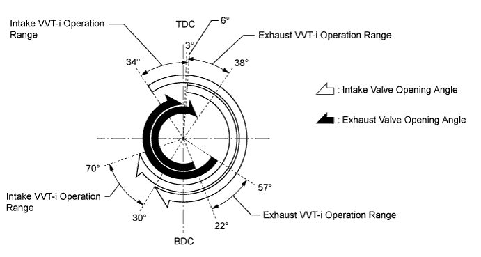
-
The Dual VVT-i system delivers excellent benefits in the different vehicle states as shown in the table below:
Operation State Objective Effect During Idling 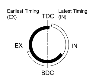
Eliminating overlap reduces blow back to the intake side.
-
Stabilized idling rpm
-
Better fuel economy
At Light Load 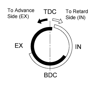
Eliminating overlap to reduce blow back to the intake side. Ensured engine stability At Medium Load 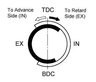
Increasing overlap increases internal EGR, reducing pumping losses.
-
Better fuel economy
-
Improved emission control
In Low to Medium Speed Range with Heavy Load 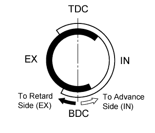
Advancing the intake valve closing timing improves volumetric efficiency. Improved torque in low to medium speed ranges In High Speed Range with Heavy Load 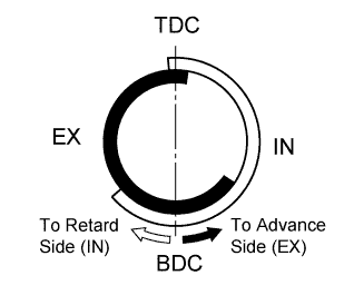
Retarding the intake valve closing timing improves volumetric efficiency. Improved output At Low Temperatures Eliminating overlap to reduce blow back to the intake side stabilizes the idling speed at fast idle.
-
Stabilized fast idle rpm
-
Better fuel economy
-
Upon Starting
-
Stopping Engine
Eliminating overlap minimizes blow back to the intake side. Improved startability -
-
-
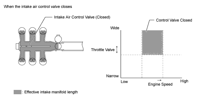
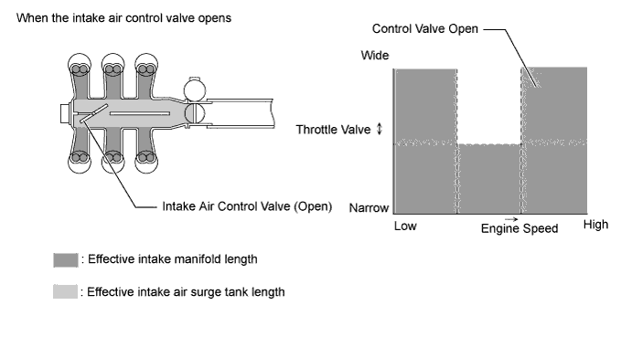
Acoustic Control Induction System (ACIS)
-
The Acoustic Control Induction System (ACIS) uses a bulkhead to divide the intake manifold, creating 2 stages. The intake air control valve in the bulkhead is opened or closed to vary the effective length of the intake manifold in accordance with the engine speed and throttle valve opening angle. This increases the power output in all ranges from low to high speed.
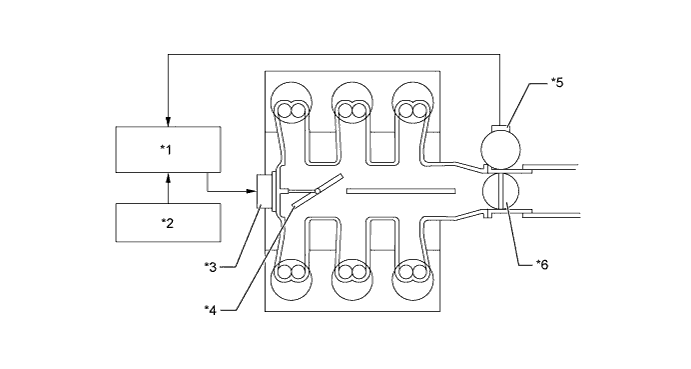
Text in Illustration *1 ECM *2 Crankshaft Position Sensor *3 ACIS Actuator *4 Intake Air Control Valve *5 Throttle Position Sensor *6 Throttle Valve
-
-
Electronic Swirl Control Valve (SCV) System
-
The electronic SCV system mainly consists of swirl control valves, SCV position sensor*, SCV actuator, and ECM.
-
*: Models with SCV position sensor
-
-
The electronic SCV system closes one of the 2 independent intake ports for each cylinder according to the engine conditions. Closing the port optimally controls the airflow in the combustion chamber and enhances the charging and combustion efficiency for low fuel consumption. The SCV system is located in the intake manifold.
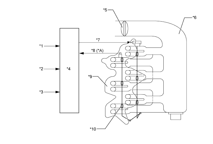
Text in Illustration *A Models with SCV Position Sensor - - *1 Crankshaft Position Sensor *2 Engine Coolant Temperature Sensor *3 Various Sensors *4 ECM *5 Throttle Valve *6 Intake Air Surge Tank *7 SCV Actuator *8 SCV Position Sensor *9 Intake Manifold *10 Swirl Control Valve
-
-
Electronic Throttle Control System-intelligent (ETCS-i)
-
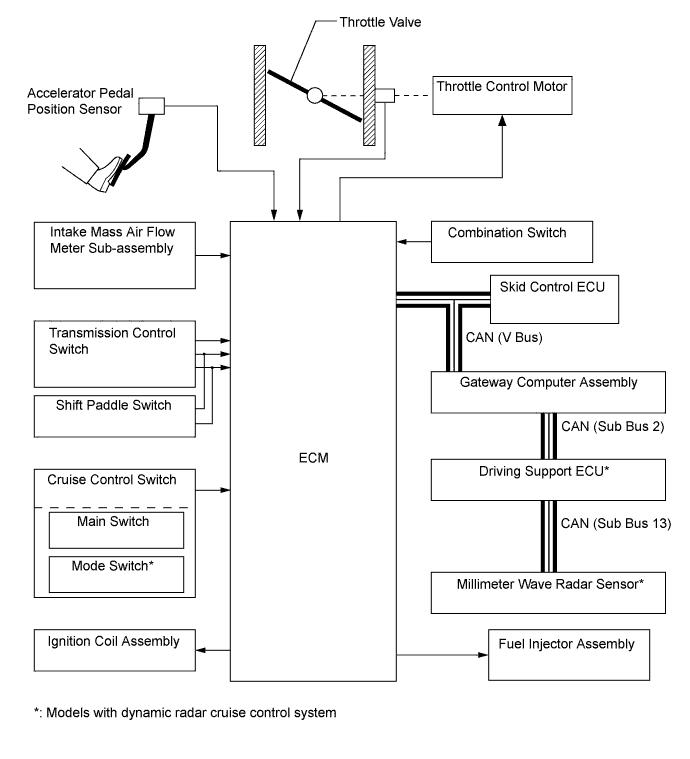
The ETCS-i is used, providing excellent throttle control in all the operating ranges. The accelerator cable has been discontinued, and an accelerator pedal position sensor has been provided on the accelerator pedal.
-
In the conventional throttle body, the throttle valve opening is determined by the amount of the accelerator pedal effort. In contrast, the ETCS-i uses the ECM to calculate the optimal throttle valve opening that is appropriate for the respective driving condition and uses a throttle control motor to control the opening.
-
The ETCS-i controls the idle speed, Traction Control (TRC), Vehicle Stability Control (VSC) system, cruise control system and dynamic radar cruise control system*.
-
*: Models with dynamic radar cruise control system
-
-
In case of an abnormal condition, this system switches to the limp mode.
-
-
Fuel Pump Control
-
The fuel pump is controlled by the fuel pump control ECU based on signals from the ECM. The fuel pump control has a fuel cut control. The fuel cut control stops the fuel pump when any of the Supplemental Restraint System (SRS) airbags have deployed.
-
-
Cooling Fan Control
-
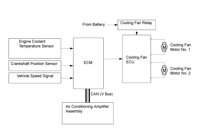
The cooling fan control system achieves an optimal fan speed in accordance with the engine coolant temperature, vehicle speed, engine speed, and air conditioning operating conditions.
-
-
Starter Control (Cranking Hold Function)
-
Once the engine switch (push start switch) is pressed, this function operates the starter until the engine starts, provided that the brake pedal is depressed.
-
This prevents application of the starter for an inadequate length of time and also prevents the engine from being cranked after it has started.
-
-
-
CONSTRUCTION
-
Intake Mass Air Flow Meter Sub-assembly
-
The intake mass air flow meter sub-assembly, which is a slot-in type, allows a portion of the intake air to flow through the detection area. By directly measuring the mass and the flow rate of the intake air, the detection precision is improved and the intake air resistance is reduced.
-
This intake mass air flow meter sub-assembly has a built-in intake air temperature sensor.
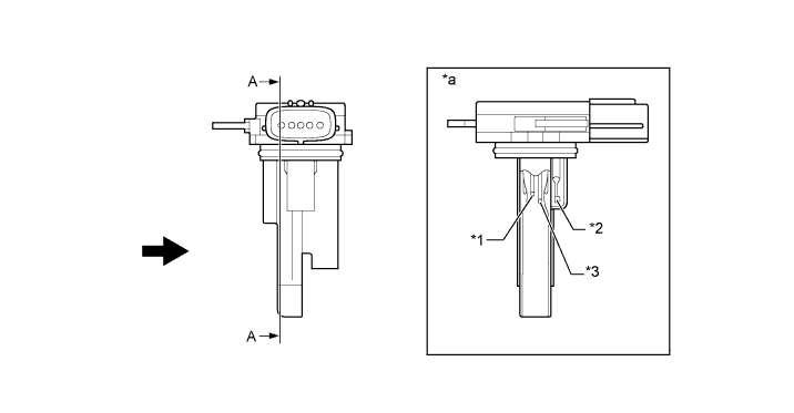
Text in Illustration *1 Platinum Hot-wire Element *2 Intake Air Temperature Sensor *3 Temperature Sensing Element - - *a A - A Cross Section - - 
Air Flow - -
-
-
Crankshaft Position Sensor
-
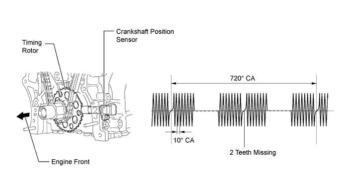
A pick-up coil type crankshaft position sensor is used. The timing rotor of the crankshaft consists of 34 teeth, with 2 teeth missing. The crankshaft position sensor outputs the crankshaft rotation signals every 10°, and the missing teeth are used to determine the top dead center.
-
-
Camshaft Position Sensor
-
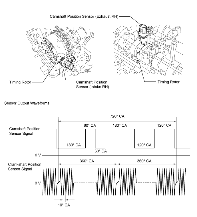
Magnetic Resistance Element (MRE) type camshaft position sensors (intake and exhaust) are used. To detect each camshaft (intake) position, a timing rotor that is secured to the camshaft (intake) in front of the camshaft timing gear assembly is used to generate 6 (3 high output, 3 low output) pulses for every 2 revolutions of the crankshaft. The timing rotor for each camshaft (exhaust) is part of the respective camshaft.
-
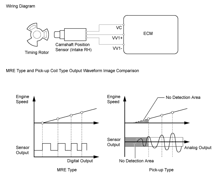
An MRE type camshaft position sensor consists of an MRE, a magnet and a sensor. The direction of the magnetic field changes due to the profile (protruding and non-protruding portions) of the timing rotor, which passes by the sensor. As a result, the resistance of the MRE changes, and the output voltage to the ECM changes to high or low. The ECM detects the camshaft position based on this output voltage.
-
-
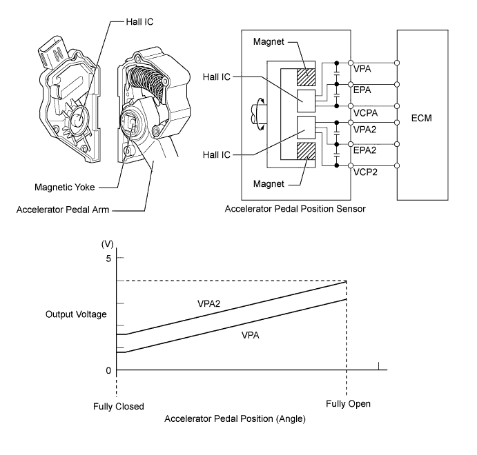
Accelerator Pedal Position Sensor
-
This non-contact type accelerator pedal position sensor uses a Hall IC, which is mounted on the accelerator pedal arm.
-
A magnetic yoke is mounted at the base of the accelerator pedal arm. This yoke rotates around the Hall IC in accordance with the amount of effort that is applied to the accelerator pedal. The Hall IC converts the changes in the magnetic flux that occur into electrical signals, and outputs them in the form of accelerator pedal position signals to the ECM.
-
The Hall IC contains 2 circuits, 1 for the main signal and 1 for the sub signal. The Hall IC converts the accelerator pedal position (angle) into electric signals that have differing characteristics and outputs them to the ECM.
-
-
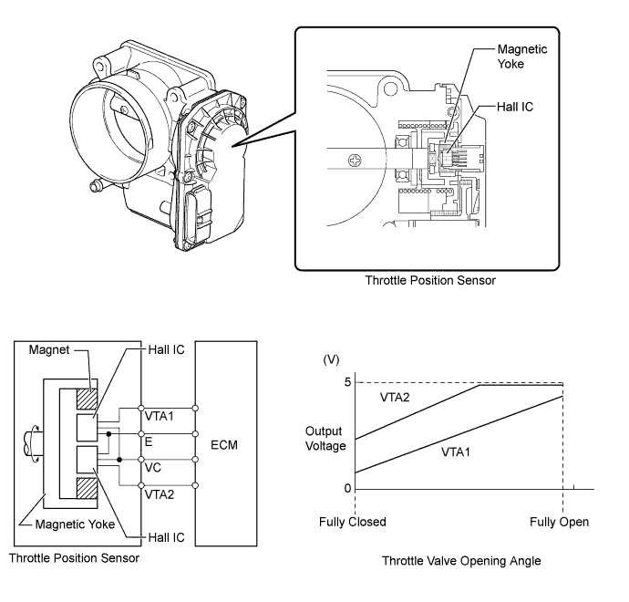
Throttle Position Sensor
-
This non-contact type throttle position sensor uses a Hall IC, which is mounted on the throttle body.
-
The Hall IC is surrounded by a magnetic yoke. The Hall IC converts the changes that occur in the magnetic flux into electrical signals, and outputs them in the form of throttle valve position signals to the ECM.
-
The Hall IC contains circuits for the main and sub signals. The Hall IC converts the throttle valve opening angle into electric signals that have differing characteristics, and outputs them to the ECM.
-
-
Knock Control Sensor (Flat Type)
-
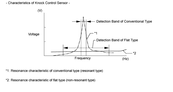
In a conventional type knock control sensor (resonant type), a vibration plate is built into the sensor. This plate has the same resonance point as the knocking* frequency of the engine block. This sensor can only detect vibration in this frequency band.
-
*: The term "knock" or "knocking" is used in this case to describe either preignition or detonation of the air fuel mixture in the combustion chamber. This preignition or detonation refers to the air fuel mixture being ignited earlier than is advantageous. This use of "knock" or "knocking" is not primarily used to refer to a loud mechanical noise that may be produced by an engine.
-
-
A flat type knock control sensor (non-resonant type) has the ability to detect vibration in a wider frequency band (from approximately 6 kHz to 15 kHz). The sensor has the following features:
-
The engine knocking frequency will vary slightly depending on the engine speed. The flat type knock control sensor can detect vibration even when the engine knocking frequency changes. Due to the use of the flat type knock control sensor, the vibration detection ability has been increased compared to a conventional type knock control sensor, and more precise ignition timing control is possible.
-
-
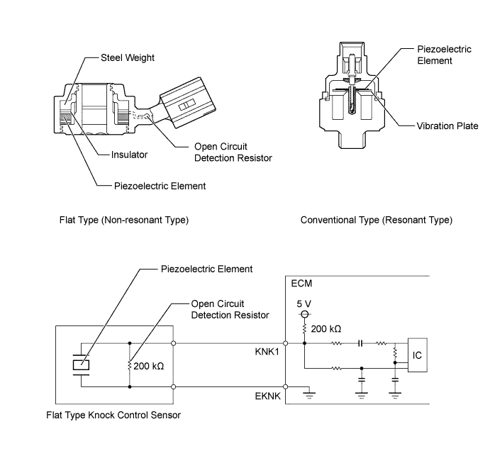
A flat type knock control sensor is installed in an engine by placing it over the stud bolt installed on the cylinder block. For this reason, a hole for the stud bolt exists in the center of the sensor.
-
In the sensor, a steel weight is located in the upper portion. An insulator is located between the weight and the piezoelectric element.
-
An open/short circuit detection resistor is integrated in the sensor. When the engine switch is on (IG), the open/short circuit detection resistor in the knock control sensor and the resistor in the ECM keep the voltage at terminal KNK1 constant. An Integrated Circuit (IC) in the ECM constantly monitors the voltage of terminal KNK1. If the open/short circuit occurs between the knock control sensor and the ECM, the voltage of terminal KNK1 will change and the ECM will detect the open/short circuit and store a Diagnostic Trouble Code (DTC).
-
Vibrations caused by knocking are transmitted to the steel weight. The inertia of this weight applies pressure to the piezoelectric element. This action generates electromotive force.
Text in Illustration *1 Steel Weight *2 Piezoelectric Element *a Inertia - - -
These knock control sensors are mounted in the specific directions and angles. To prevent the right and left bank connectors from being interchanged, make sure to install each sensor in its prescribed direction. For details, refer to the Repair Manual.
-
-
Air Fuel Ratio Sensor and Oxygen Sensor
-
A planar type air fuel ratio sensor and a cup type oxygen sensor are used. The basic construction of the oxygen sensor and the air fuel ratio sensor is the same. However, they are divided into the cup type and the planar type in accordance with the different types of heater construction used.
-
The planar type air fuel ratio sensor uses alumina, which excels in heat conductivity and electrical insulation, to integrate the sensor element with a heater, thus improving the warmup performance of the sensor.
-
The cup type oxygen sensor contains a sensor element that surrounds the heater.
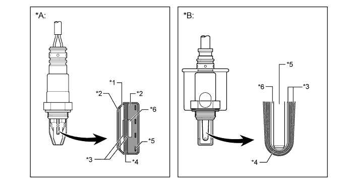
Text in Illustration *A Planar Type Air Fuel Ratio Sensor *B Cup Type Oxygen Sensor *1 Diffusion Resistance Layer *2 Alumina *3 Platinum Electrode *4 Sensor Element (Zirconia) *5 Heater *6 Atmosphere -
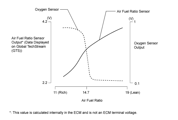
As illustrated below, the conventional oxygen sensor is characterized by a sudden change in its output voltage at the threshold of the stoichiometric air fuel ratio (14.7:1). In contrast, the air fuel ratio sensor data is approximately proportionate to the existing air fuel ratio. The air fuel ratio sensor converts the oxygen density to current and sends it to the ECM. As a result, the detection precision of the air fuel ratio has been improved. The air fuel ratio sensor data can be viewed using an Global Tech Stream (GTS).
-
-
Camshaft Timing Oil Control Valve Assembly
-
This camshaft timing oil control valve assembly controls the spool valve using duty-cycle control from the ECM. This allows hydraulic pressure to be applied to the camshaft timing gear assembly or camshaft timing exhaust gear assembly advance or retard side. When the engine is stopped, the camshaft timing oil control valve assembly (intake) will move to the retard position, and the camshaft timing oil control valve assembly (exhaust) will move to the advance position.
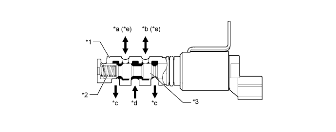
Text in Illustration *1 Sleeve *2 Spring *3 Spool Valve - - *a To Camshaft Timing Gear Assembly (Advance Side) *b To Camshaft Timing Gear Assembly (Retard Side) *c Drain *d Oil Pressure *e On the camshaft timing oil control valve (exhaust), the advance and retard sides are reversed. - -
-
-
Ignition Coil Assembly
-
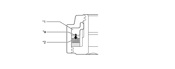
The Direct Ignition System (DIS) provides 6 ignition coil assemblies, one for each cylinder. The spark plug caps, which provide contact to spark plugs, are integrated with the ignition coil assembly. Also, an igniter is enclosed to simplify the system.
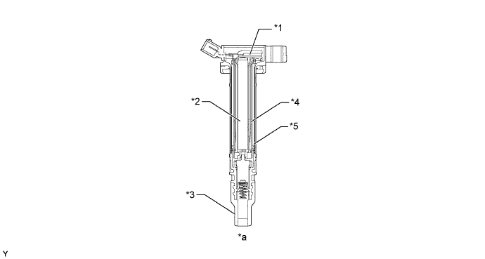
Text in Illustration *1 Igniter *2 Iron Core *3 Plug Cap *4 Secondary Coil *5 Primary Coil - - *a Cross Section - -
-
-
Spark Plug
-
Long-reach type spark plugs are used. This type of spark plugs allows the area of the cylinder head sub-assembly that receives the spark plugs to be made thick. Thus, the water jacket can be extended near the combustion chamber, which contributes to cooling performance.
-
The triple ground electrode type iridium-tipped spark plugs are used to achieve a 96000 km (60000 miles) maintenance interval. By making the center electrode of iridium, it is possible to achieve superior ignition performance and durability when compared to platinum-tipped spark plugs. Furthermore, two ground electrodes have been added to further enhance ignitability, wear resistance, and fouling resistance.
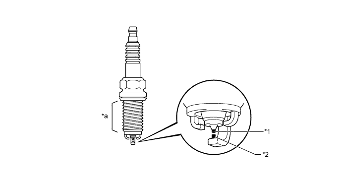
Text in Illustration *1 Iridium Tip *2 Platinum Tip *a Long-reach - -
-
-
-
OPERATION
-
Dual VVT-i System
-
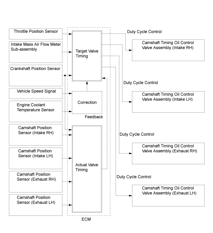
Based on engine speed, intake air mass, throttle position and engine coolant temperature, the ECM calculates optimal valve timing for all driving conditions. The ECM also controls the camshaft timing oil control valve assemblies. In addition, the ECM uses signals from the camshaft position sensors and the crankshaft position sensor to detect the actual valve timing, thus providing feedback control to achieve the target valve timing.
-
When the camshaft timing oil control valve assembly is positioned as illustrated below by the advance signals from the ECM, the resultant oil pressure is applied to the timing advance side vane chamber to rotate the camshaft in the timing advance direction:
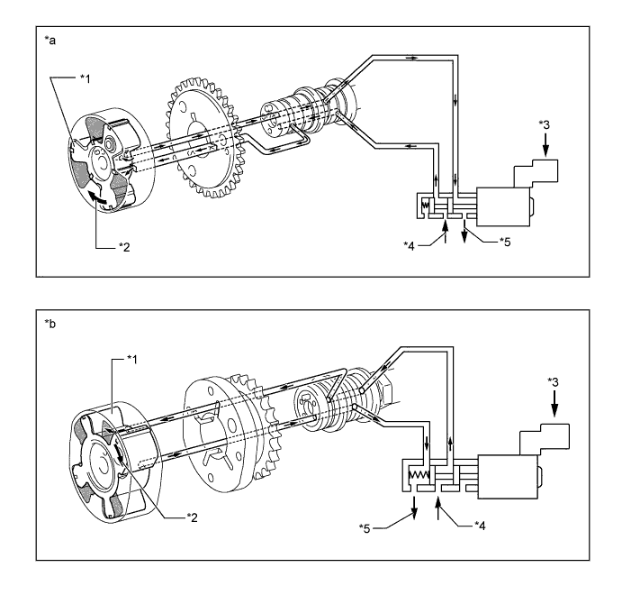
Text in Illustration *1 Vane *2 Rotation Direction *3 ECM *4 In (Oil Pressure) *5 Drain (Oil Pressure) - - *a Advance Side Operation Intake Side *b Advance Side Operation Exhaust Side -
When the camshaft timing oil control valve assembly is positioned as illustrated below by the retard signals from the ECM, the resultant oil pressure is applied to the timing retard side vane chamber to rotate the camshaft in the timing retard direction:
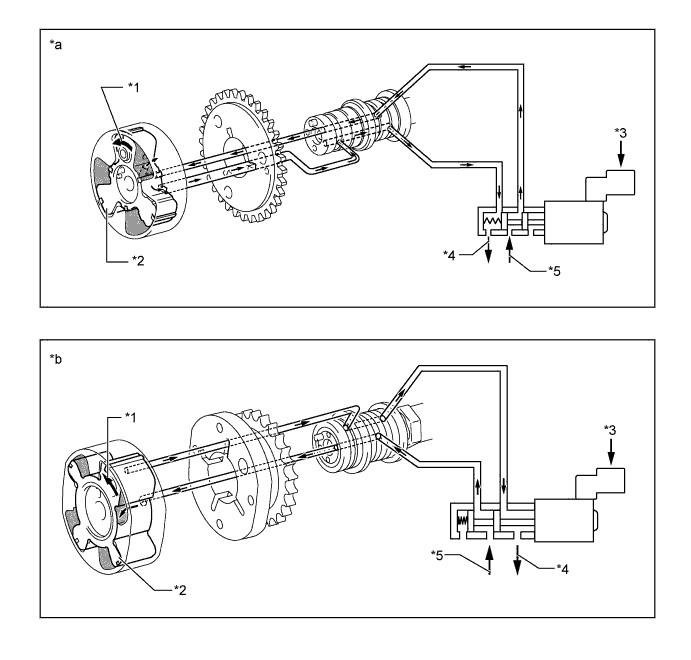
Text in Illustration *1 Rotation Direction *2 Vane *3 ECM *4 Drain (Oil Pressure) *5 In (Oil Pressure) - - *a Retard Side Operation Intake Side *b Retard Side Operation Exhaust Side -
After reaching the target timing, the engine valve timing is maintained by keeping the camshaft timing oil control valve assembly in the neutral position unless the engine operating conditions change. This maintains the engine valve timing at the desired target position by preventing the engine oil from running out of the camshaft timing oil control valve assembly.
-
-
Acoustic Control Induction System (ACIS)
-
While the engine is running at medium speed under high load, the ECM causes the actuator to close the control valve. As a result, the effective length of the intake manifold is lengthened and the intake efficiency, in the medium speed range, is improved due to the dynamic effect (inertia) of the intake air, thereby increasing power output.
-
Under any condition except when the engine is running at medium speed under high load, the ECM causes the actuator to open the control valve. When the control valve is open, the effective length of the intake air surge tank is shortened and peak intake efficiency is shifted to the low-to-high engine speed range, thus providing greater output at low-to-high engine speeds.
-
-
Electronic Swirl Control Valve (SCV) System
-
A Swirl Control Valve (SCV) is used for each cylinder. Each cylinder has 2 independent intake ports, 1 for each intake valve. The SCV is able to open or close one of these ports. The opening and closing of the swirl control valves is controlled by the ECM.
-
The SCVs for the left and right bank intake ports are connected by a link mechanism. They are activated by a single SCV actuator (compact DC motor).
-
The ECM activates the SCV actuator to open or close the SCVs based on engine speed, engine coolant temperature and driving conditions.
-
Closing one of the ports accelerates the speed of the intake air that flows through the other port, strengthening the turbulence in the combustion chamber. This results in enhanced atomization of fuel when the coolant temperature is low, thus stabilizing combustion.
-
When the engine is operating at low speed and low load conditions, the SCV remains fully closed. Thus, only one port is used for intake, in order to promote the mixture of air and fuel. This also accelerates the intake flow speed, which enhances combustion and fuel economy.
-
When the engine is operating at high load conditions, the SCV opens to allow the intake of air to each cylinder through both ports. This increases the intake air volume and enhances charging efficiency. At the same time, this creates a vertical swirl current (tumble current) in the combustion chamber to promote the mixture of air and fuel, thus improving performance.
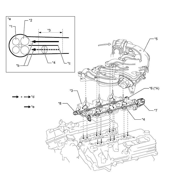
Text in Illustration *A Models with SCV Position Sensor - - *1 Exhaust Valve *2 Intake Valve *3 Intake Manifold *4 Swirl Control Valve *5 Intake Air Surge Tank *6 SCV Position Sensor *7 SCV Actuator *8 Link Mechanism *a Intake Port Image *b Intake Port Division Continues *c Division of Intake Port Starts *d Flow of Air with Swirl Control Valve Open *e Flow of Air with Swirl Control Valve Closed - -
-
-
Fuel Pump Control
-
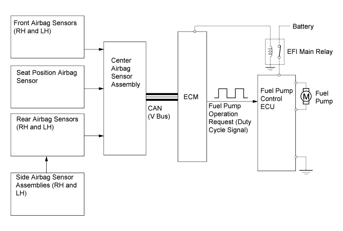
In this vehicle, there are 2 types of fuel pump controls. The fuel pump is controlled to an optimum speed to match the engine operating conditions, and the fuel pump operation is stopped when the SRS airbags deploy.
-
The ECM transmits a fuel pump operation request signal to the fuel pump control ECU that corresponds to the engine operating conditions. The fuel pump control ECU receives this request signal and controls the speed of the fuel pump. As a result, under light engine loads, fuel pump speed is kept low to reduce electric power loss.
-
A fuel cut control is used to stop the fuel pump when any of the SRS airbags deploys. In this control, if an airbag deployment signal from the center airbag sensor assembly is detected by the ECM, the ECM will turn off the circuit opening relay. As a result, the power supply to the fuel pump control ECU is stopped, causing the fuel pump to stop operating. After the fuel cut control has been activated, turning the engine switch (push start switch) from off to on (IG) cancels the fuel cut control, and the engine can be restarted.
-
The fuel pump control ECU controls fuel pump speed by receiving a duty cycle signal (FPC terminal input) from the ECM.
-
-
Cooling Fan Control
-
The ECM calculates the cooling fan speed in accordance with the engine coolant temperature, vehicle speed, engine speed and air conditioning operating conditions, and sends the signals to the cooling fan ECU. Upon receiving the signals from the ECM, the cooling fan ECU actuates the cooling fan motor.
-
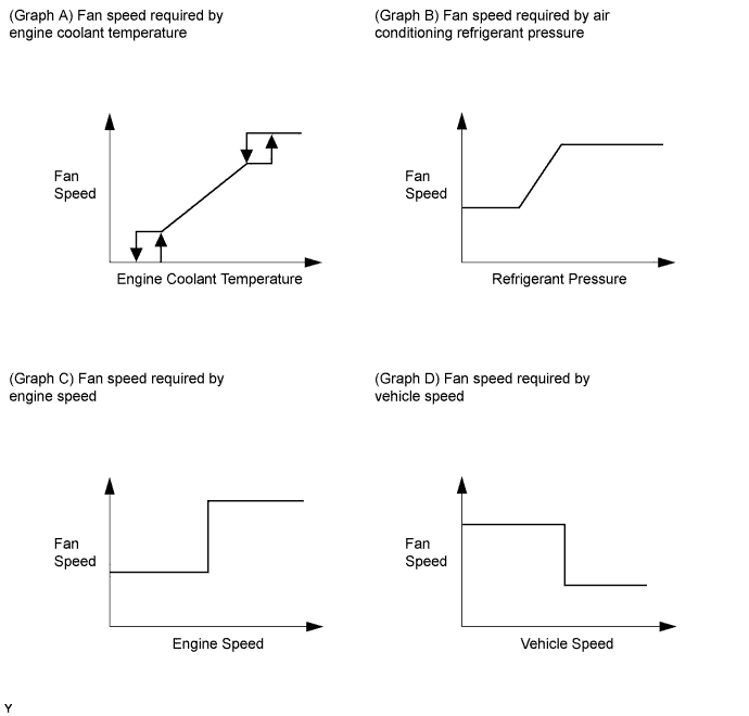
As illustrated below, the ECM determines the required fan speed by selecting the fastest fan speed from among the following:
-
The graphs below show the fan speed required by the engine coolant temperature (Graph A), the fan speed required by the air conditioning refrigerant pressure (Graph B), the fan speed required by the engine speed (Graph C), and the fan speed required by the vehicle speed (Graph D).
-
-
ETCS-i
-
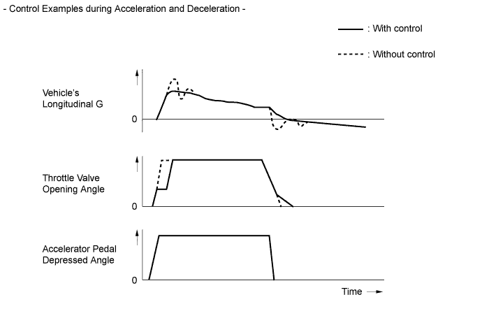
The ECM drives the throttle control motor by determining the target throttle valve opening in accordance with the respective operating condition.
-
The ECM controls the throttle to an optimal throttle valve opening that is appropriate for the driving conditions such as the amount of accelerator pedal effort and the engine speed in order to achieve excellent throttle control and comfort in all operating ranges.
-
The ECM controls the throttle valve in order to constantly maintain an ideal idle speed.
-
As part of the TRC, the throttle valve opening angle is reduced by a demand signal sent from the skid control ECU to the ECM. This demand signal is sent if an excessive amount of slippage occurs at a drive wheel, thus ensuring vehicle stability and applying an appropriate amount of power to the road.
-
In order to bring the effectiveness of the VSC into full play, the throttle valve angle is regulated through a coordination control by the skid control ECU and the ECM.
-
In situations in which low-μ (low friction coefficient) road surface conditions can be anticipated, such as when driving in the snow, the rate of throttle valve opening can be controlled to help vehicle stability while driving on the slippery surface. This is accomplished by turning on SNOW mode. Pressing the SNOW side of the combination switch activates this mode. This mode modifies the relationship and reaction of the throttle to the accelerator pedal, and assists the driver by reducing the engine output from that of a normal level.
-
The ECM directly actuates the throttle valve for operation of the cruise control.
-
On the models with dynamic radar cruise control system, the dynamic radar cruise control uses a millimeter wave radar sensor and driving support ECU to determine the distance, direction, and relative speed of a vehicle ahead. Thus, the system can effect deceleration control, follow-up control, constant speed control, and acceleration control. To make these controls possible, the ECM controls the throttle valve.
-
-
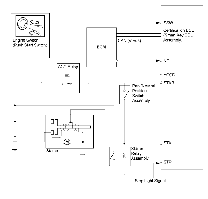
Starter Control (Cranking Hold Function)
-
When the driver pushes the engine switch (push start switch) once and the certification ECU (smart key ECU assembly) detects a start signal, the certification ECU (smart key ECU assembly) will output ACCD and STAR signals and begin cranking. Also, the driver can continue cranking for up to 30 seconds by pushing and holding the engine switch.
-
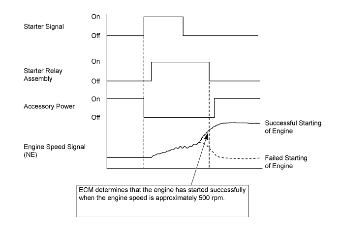
If the engine speed reaches approximately 500 rpm, the ECM will judge that the engine has started and will send a signal to the certification ECU (smart key ECU assembly) using CAN communication. The certification ECU (smart key ECU assembly) will then stop the operation of the starter.
-
If CAN communication is cut between the certification ECU (smart key ECU assembly) and the ECM, the certification ECU (smart key ECU assembly) will receive an engine speed signal (NE) directly from the ECM and will stop the operation of the starter.
-
This system will cut off the power current which activates the accessories while the engine is being cranked. This prevents the intermittent blinking of the accessory lights caused by the voltage instability that occurs during engine cranking.
-
This system has the following protections:
-
The starter will not operate if the engine is operating normally.
-
If the engine switch (push start switch) is pushed and held, cranking will stop once the engine speed reaches a pre-determined level. This prevents the starter from over-revving.
-
If the engine does not start even after approximately 6 seconds of starter operation, the certification ECU (smart key ECU assembly) will cancel the starter relay output. Furthermore, if the engine does not start after the engine switch has been pushed and held and cranking has continued for 30 seconds, cranking will be canceled in order to protect the starter.
-
It will not be possible to operate the starter for 2 seconds after engine starting has failed and cranking has been canceled. This helps to protect the starter.
-
-
-