CAN COMMUNICATION SYSTEM PARTS LOCATION
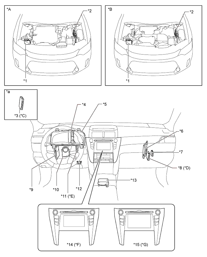
| *A | Models with 2GR-FE Engine | *B | Models with 2AR-FE Engine |
| *C | Models with Smart Entry and Start System | *D | Models with TOYOTA Parking Assist-sensor System |
| *E | Models with Intelligent AFS | *F | Models with Multimedia System |
| *G | Models with Navigation System | - | - |
| *1 | Brake Actuator Assembly - Skid Control ECU |
*2 | ECM |
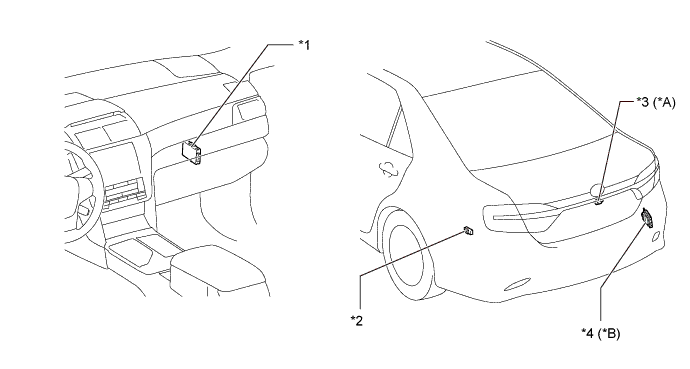
| *3 | Certification ECU (Smart Key ECU Assembly) | *4 | Power Steering ECU Assembly |
| *5 | Combination Meter Assembly | *6 | Air Conditioning Amplifier Assembly |
| *7 | Network Gateway ECU | *8 | Clearance Warning ECU Assembly |
| *9 | Main Body ECU (Multiplex Network Body ECU) | *10 | Steering Sensor |
| *11 | Headlight Swivel ECU Assembly | *12 | DLC3 |
| *13 | Airbag Sensor Assembly - Yawrate Sensor |
*14 | Radio and Display Receiver Assembly |
| *15 | Navigation Receiver Assembly | - | - |
| *a | Refer to Service Bulletin for the installation position of the part. | - | - |
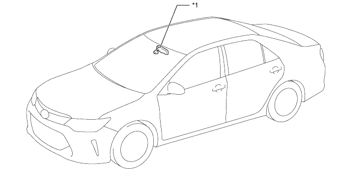
| *1 | Inner Rear View Mirror Assembly | - | - |
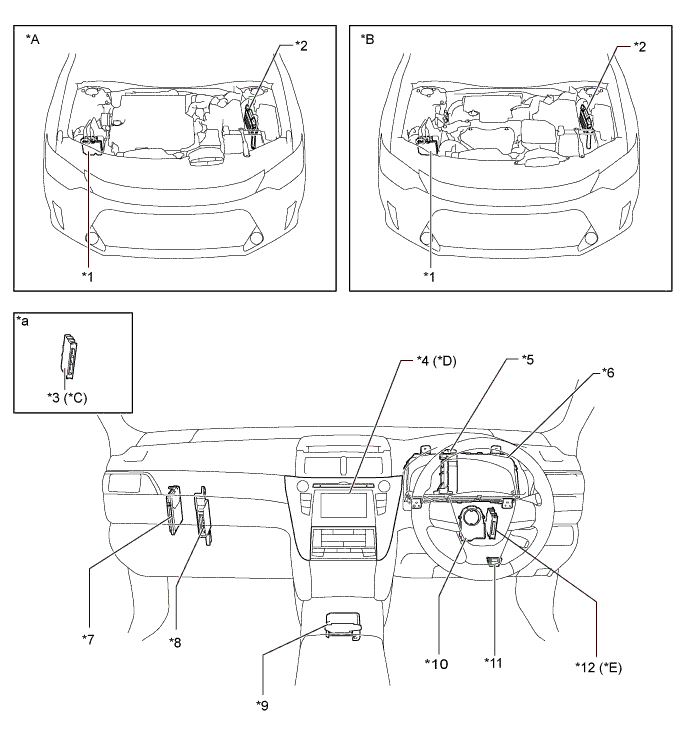
| *A | Models with 2GR-FE Engine | *B | Models with 2AR-FE Engine |
| *C | Models with Smart Entry and Start System | *D | Models with Multimedia System |
| *E | Models with TOYOTA Parking Assist-sensor System | - | - |
| *1 | Brake Actuator Assembly - Skid Control ECU |
*2 | ECM |
| *3 | Certification ECU (Smart Key ECU Assembly) | *4 | Radio and Display Receiver Assembly |
| *5 | Power Steering ECU Assembly | *6 | Combination Meter Assembly |
| *7 | Main Body ECU (Multiplex Network Body ECU) | *8 | Air Conditioning Amplifier Assembly |
| *9 | Airbag Sensor Assembly - Yawrate Sensor |
*10 | Steering Sensor |
| *11 | DLC3 | *12 | Clearance Warning ECU Assembly |
| *a | Refer to the Service Bulletin for the installation position of the part. | - | - |
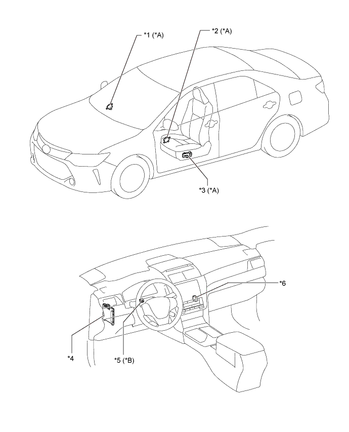
| *A | Models with Seat Position Memory System | *B | Models with Power Tilt and Telescopic System |
| *1 | Outer Mirror Control ECU Assembly (RH) | *2 | Outer Mirror Control ECU Assembly (LH) |
| *3 | Position Control ECU and Switch Assembly | *4 | Main Body ECU (Multiplex Network Body ECU) |
| *5 | Multiplex Tilt and Telescopic ECU | *6 | CAN Junction Connector No. 5 |
| *A | Models with Multimedia System and Parking Assist Monitor System (without Parallel Parking Assist Function) | *B | Models with Blind Spot Monitor System |
| *1 | Network Gateway ECU | *2 | CAN No. 9 Junction Connector |
| *3 | Rear Television Camera Assembly | *4 | Blind Spot Monitor Sensor RH |