AUTOMATIC TRANSAXLE SYSTEM DETAILS
-
SYSTEM CONTROL
-
The electronic control system of the U241E automatic transaxle consists of the controls listed below:
Control Function Clutch Pressure Control Achieves smooth shift characteristics by minutely controlling clutch pressure in accordance with engine output and driving conditions. Line Pressure Control Actuates shift solenoid valve SLT to control the line pressure in accordance with information from the ECM and the operating conditions of the transaxle. Engine Torque Control Retards the engine ignition timing temporarily to improve shift feeling during up or down shifting. Shift Control in Uphill/Downhill Traveling Achieves smooth driving by controlling shift-up and shift-down when traveling uphill or downhill. Lock-up Timing Control The ECM sends current to shift solenoid valve DSL based on signals from various sensors to engage or disengage the lock-up clutch. Flex Lock-up Clutch Control Controls shift solenoid valve DSL, provides an intermediate mode between the on and off states of the lock-up clutch, and increases the operating range of the lock-up clutch to improve fuel economy. N to D Squat Control When the shift lever is moved from N to D, the gear is temporarily moved to the 2nd and then to the 1st to reduce vehicle squat. Multi-mode Automatic Transmission The ECM appropriately controls the automatic transaxle in accordance with the range selected while the shift lever is in S. Shift Lock System The shift lock mechanism prevents the shift lever from being moved to any position other than P, unless the ignition switch is ON, and the brake pedal is depressed. Fail-safe If a malfunction is detected in the sensors or solenoids, the ECM performs fail-safe control to prevent the vehicle drivability from being affected significantly. Diagnosis When the ECM detects a malfunction, the ECM records the malfunction and memorizes the information that relates to the fault. -
Clutch Pressure Control
-
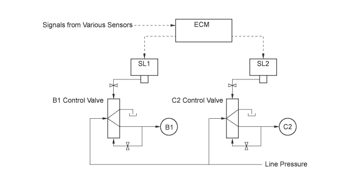
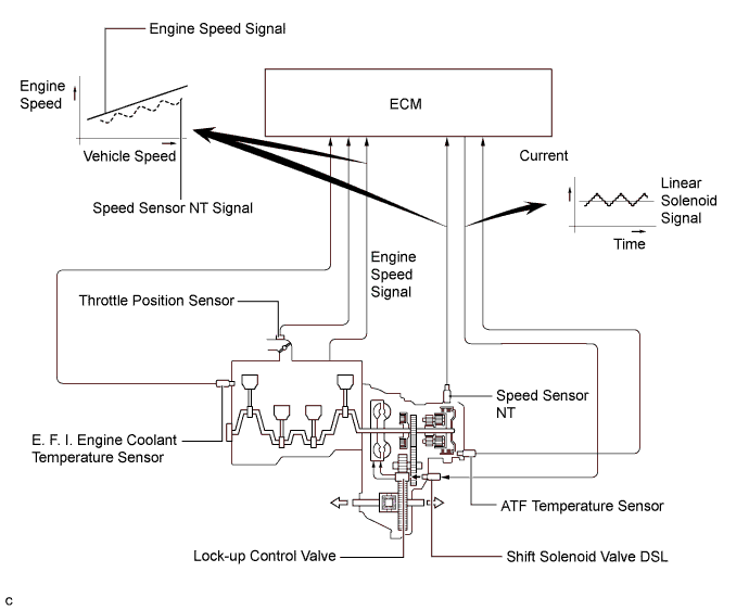
A clutch pressure control is used for shifting from the 2nd to 3rd gear. Shift solenoid valves SL1 and SL2 are actuated in accordance with the signals from the ECM, and this output pressure is guided directly to the control valves B1 and C2 in order to regulate the line pressure that acts on the 2nd brake (B1) and direct clutch (C2). As a result, high response levels and excellent shift characteristics have been achieved.
-
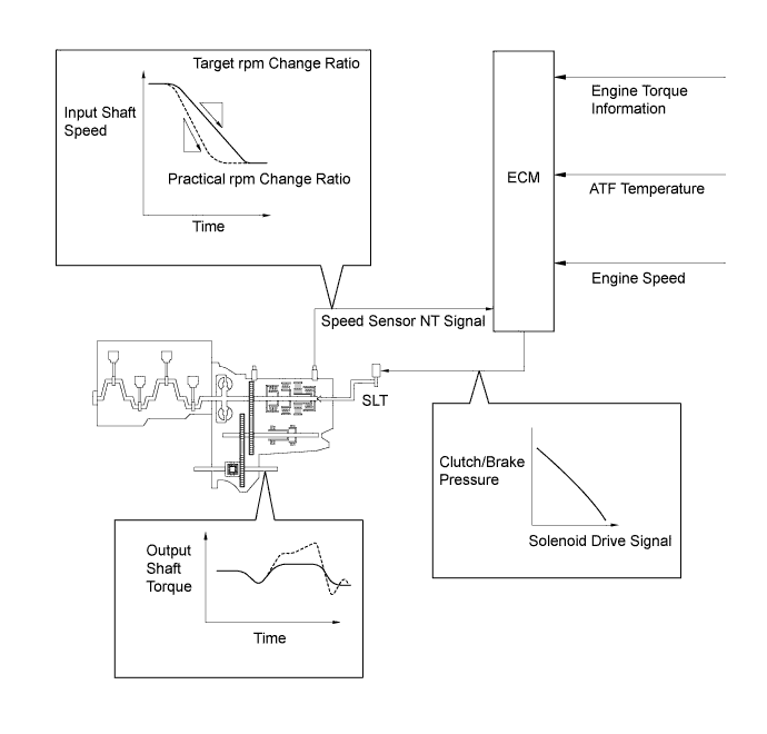
Shift solenoid valve SLT is used for control of clutch pressure. The ECM monitors the signals from various sensors such as the speed sensor NT, allowing shift solenoid valve SLT to minutely control the clutch pressure in accordance with engine output and driving conditions. As a result, smooth shift characteristics have been achieved.
-
-
Line Pressure Control
-
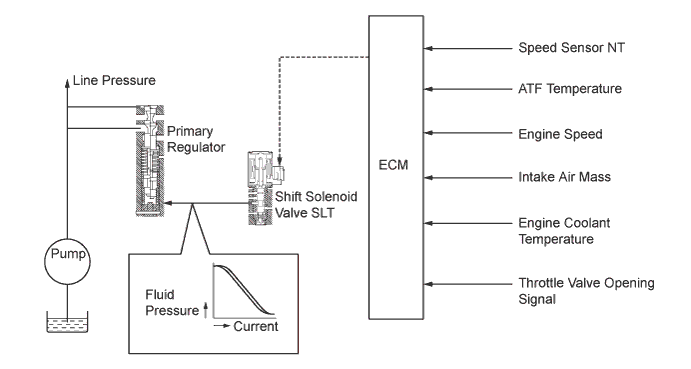
Through the use of shift solenoid valve SLT, the line pressure is appropriately controlled in accordance with the engine torque information, as well as with the internal operating conditions of the torque converter clutch and the transaxle. Accordingly, the line pressure can be controlled minutely in accordance with the engine output, traveling condition, and the ATF temperature, thus achieving smooth shift characteristics and regulating the workload in the oil pump.
-
-
Lock-up Timing Control
-
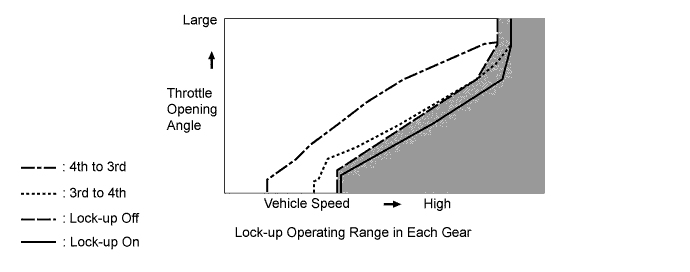
The ECM uses lock-up timing control in order to improve the fuel economy in 4th gear when the shift lever is in D.
Lock-up Operation: Gear Shift Lever Position D S 1st X X 2nd X X 3rd X X 4th ○ ○ Tech Tips
○: Operates
X: Does not operate
-
-
Flex Lock-up Clutch Control
-
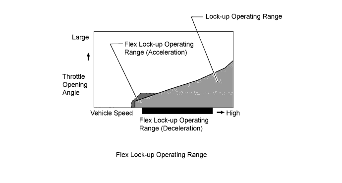
During acceleration, the partial control of the power transmission between the lock-up clutch and torque converter greatly boosts the transmission efficiency in accordance with the driving conditions, improving the fuel economy.
-
Even when the vehicle is decelerating (the accelerator pedal is released), flex lock-up clutch control operates. Therefore, the fuel-cut area of the engine has been expanded and fuel-economy has been improved.
-
For flex lock-up control, H infinity (H∞) control theory is used to achieve a high level of system stability and response to various characteristic changes.
-
The operating range of the lock-up clutch has been expanded to operate from low speeds to improve fuel economy.
Flex Lock-up Operation: Gear Shift Lever Position or Range D or S4 S3 1st X X 2nd X X 3rd ○ ○* 4th ○ - Tech Tips
○: Operates
X: Does not operate
-: Not applicable
*: Flex lock-up clutch control operates only when the vehicle decelerates.
-
-
Shift Control in Uphill/Downhill Traveling
-
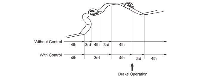
This control helps minimize the gear shifting when the driver operates the accelerator pedal while driving on a winding uphill or downhill road in order to ensure a smooth drive.
-
When the ECM detects uphill travel, it prohibits upshifting to the 4th after downshifting to the 3rd.
-
If a signal indicating that the driver has operated the brake pedal is input while the ECM detects downhill travel, it downshifts from the 4th to 3rd.
-
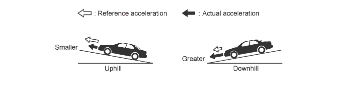
The actual acceleration calculated from the speed sensor signals is compared with the reference acceleration (based on level road travel) stored in the ECM to determine uphill or downhill travel.
-
-
Multi-mode Automatic Transmission
-
The driver can select the desired shift range by moving the shift lever to "+" (forwards) or to "-" (backwards) while in S.
-
The multi-mode automatic transmission is designed to allow the driver to switch the gear ranges.
-
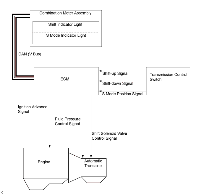
An S mode indicator light which illuminates when the shift lever is in S and a shift indicator light which indicates the shift range have been provided in the combination meter.
-
The driver can select S mode by moving the shift lever to S. At this time, the 3rd shift range will be selected. Then, the shift range changes sequentially, as the driver moves the shift lever to "+" (forwards) or to "-" (backwards).
-
Under this control, the ECM performs shift control within the usable gear range that the driver selects. As with an ordinary automatic transaxle, it shifts to 1st gear when the vehicle is stopped.
-
The shift lever position and the shift range are indicated by the shift indicator light in the combination meter assembly (the shift range is shown only when the shift lever is in S, and it is not shown when the shift lever is in P, R, N or D).
-
When the shift lever is in S, the S mode indicator light in the combination meter assembly illuminates. The shift indicator light indicates the shift range that the driver has selected.
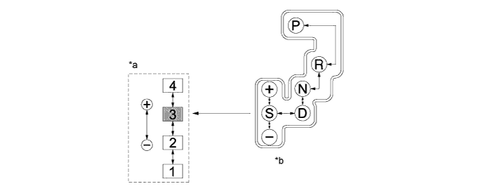
Text in Illustration *a Transition of Shift Ranges *b Shift Pattern 
Default Shift Range - - Usable Gear Chart Shift Range Shift Range Indicator Usable Gear S4 4 1st to 4th S3 3 1st to 3rd S2 2 1st to 2nd S1 1 1st
-
-
Shift Lock System
-
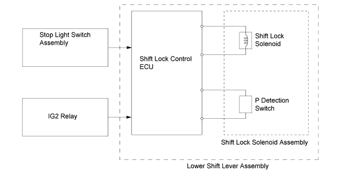
The shift lock system is controlled by the shift lock control ECU.
-
The shift lock mechanism prevents the shift lever from being moved to any position other than P, unless the ignition switch is ON, and the brake pedal is depressed. This mechanism helps to prevent unintentional acceleration.
-
The shift lock system mainly consists of the shift lock control ECU, shift lock solenoid assembly and shift lock release button.
-
The shift lock control ECU uses the P detection switch to detect the shift lever position, and receives inputs from the stop light switch assembly and IG2 relay. Upon receiving these signals, the shift lock control ECU turns on the shift lock solenoid in order to release the shift lock.
-
-
-
CONSTRUCTION
-
Torque Converter Assembly
-
This torque converter assembly has appropriately designed fluid passages and impeller configuration, resulting in substantially enhanced transmission efficiency to ensure good starting, acceleration and fuel economy.
-
Furthermore, a hydraulically operated lock-up mechanism which cuts power transmission losses due to slippage at medium and high speeds is used.
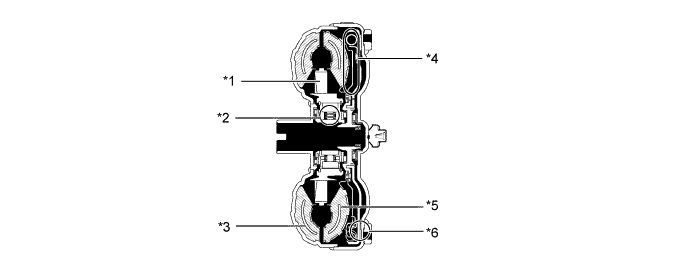
Text in Illustration *1 Stator *2 1-way Clutch *3 Pump Impeller *4 Lock-up Damper *5 Turbine Runner *6 Lock-up Clutch
-
-
Oil Pump Assembly
-
The oil pump assembly is combined with the torque converter clutch. It lubricates the planetary gear units and supplies operating pressure to the hydraulic control.
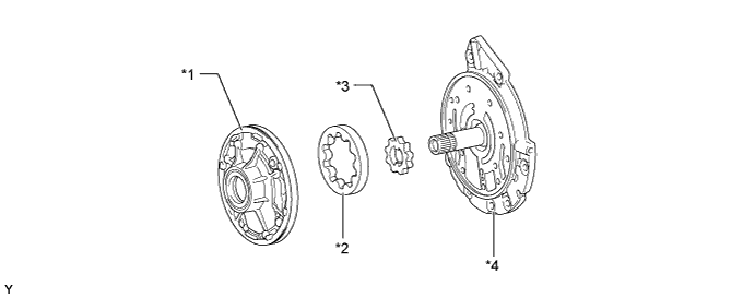
Text in Illustration *1 Oil Pump Body *2 Front Oil Pump Driven Gear *3 Front Oil Pump Drive Gear *4 Stator Shaft Assembly
-
-
Planetary Gear Unit
-
The counter drive and driven gears are placed in front of the front planetary gear unit and the underdrive planetary gear unit is placed above the counter shaft. Furthermore, the number of brakes and 1-way clutches has been minimized to achieve a compact and high-capacity structure.
-
A centrifugal fluid pressure canceling mechanism is used in the direct clutch (C2) and underdrive clutch (C3) that are applied when shifting from 2nd to 3rd and from 3rd to 4th.
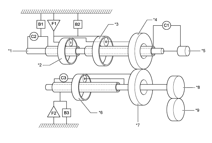
Text in Illustration *1 Intermediate Shaft *2 Rear Planetary Gear Unit *3 Front Planetary Gear Unit *4 Counter Drive Gear *5 Input Shaft *6 Underdrive Planetary Gear Unit *7 Counter Driven Gear *8 Differential Drive Pinion *9 Ring Gear - -
-
-
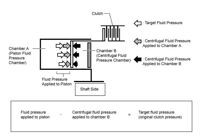
Centrifugal Fluid Pressure Canceling Mechanism
-
For the following reason, the centrifugal fluid pressure canceling mechanism is used on the direct clutch (C2) and underdrive clutch (C3):
-
Clutch shifting operation is affected not only by the valve body controlling fluid pressure but also by the centrifugal fluid pressure that is present due to the fluid in the clutch piston oil pressure chamber. The centrifugal fluid pressure canceling mechanism uses chamber B to reduce the effect applied to chamber A. As a result, smooth shifting with excellent response has been achieved.
Text in Illustration *1 Direct Clutch (C2) *2 Piston *3 Clutch *4 Chamber A *5 Chamber B *6 Underdrive Clutch (C3) -
Chamber B is filled by fluid supplied to the shaft for lubrication. As a result of filling chamber B, there is the same amount of fluid pressure due to centrifugal force on both sides of the piston. This cancels the effect of fluid pressure on the piston due to centrifugal force. Accordingly, it is not necessary to discharge the fluid through the use of a check ball, and highly responsive and smooth shifting characteristics are achieved.
-
-
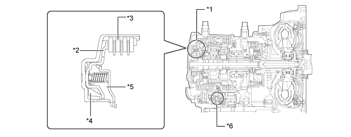
Valve Body Unit
-
The valve body consists of the upper and lower valve bodies and 5 shift solenoid valves.
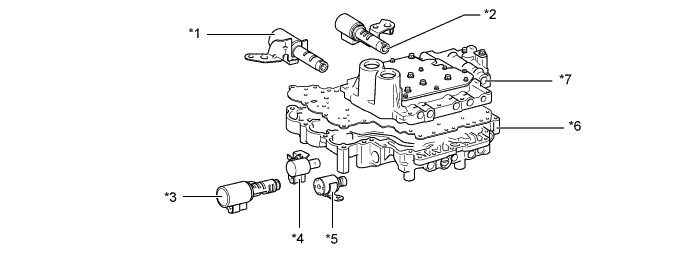
Text in Illustration *1 Shift Solenoid Valve SL1 *2 Shift Solenoid Valve SLT *3 Shift Solenoid Valve SL2 *4 Shift Solenoid Valve DSL *5 Shift Solenoid Valve S4 *6 Lower Valve Body *7 Upper Valve Body - - 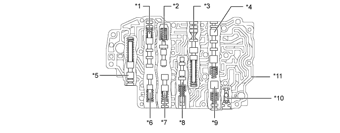
Text in Illustration *1 Lock-up Relay Valve *2 Lock-up Control Valve *3 2nd Regulator Valve *4 C2 Lock Valve *5 Solenoid Modulator Valve *6 B3 Orifice Control Valve *7 B1 Lock Valve *8 Clutch Apply Control Valve *9 C2 Exhaust Check Valve *10 3-way Check Valve *11 Upper Valve Body - - 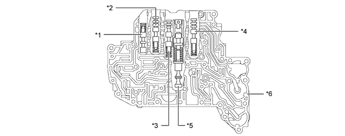
Text in Illustration *1 3-4 Shift Valve *2 B1 Control Valve *3 B2 Control Valve *4 C2 Control Valve *5 Primary Regulator Valve *6 Lower Valve Body -
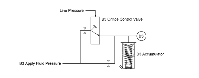
Apply orifice control, which controls the flow volume to the underdrive brake (B3), is used. This control is effected by the B3 orifice control valve. The B3 orifice control valve has been provided for the underdrive brake (B3), which is applied when shifting from the 4th to 3rd. The B3 orifice control valve is controlled by the amount of line pressure in accordance with shifting conditions, and the flow volume of the fluid supplied to the underdrive brake (B3) is controlled by varying the size of the control valve's apply orifice.
-
-
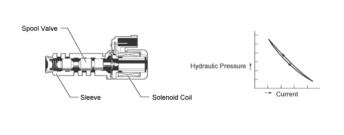
Shift Solenoid Valves SL1, SL2 and SLT
-
In order to supply hydraulic pressure proportional to the current that flows to the solenoid coil, shift solenoid valves SL1, SL2, and SLT are provided.
-
These valves linearly control the line pressure and clutch and brake engagement pressure based on the signals from the ECM.
Function of Shift Solenoid Valves SL1, SL2, and SLT Shift Solenoid Valve Function SL1
-
2nd brake (B1) pressure control
-
Lock-up clutch pressure control
SL2 Direct clutch (C2) pressure control SLT
-
Line pressure control
-
Secondary pressure control
-
-
-
Shift Solenoid Valves S4 and DSL
-
These shift solenoid valves use a 3-way solenoid valve.
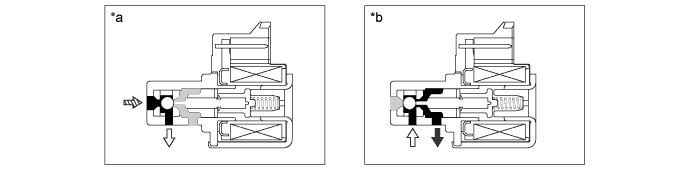
Text in Illustration *a Solenoid Valve On *b Solenoid Valve Off 
Drain 
Control Pressure 
Line Pressure - - -
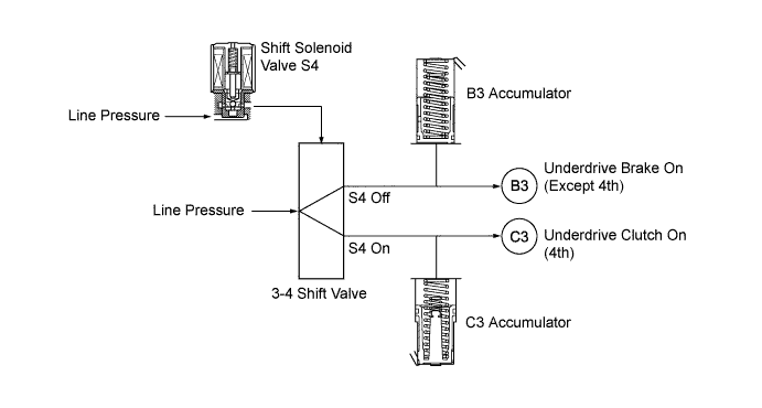
When set to on, shift solenoid valve S4 controls the 3-4 shift valve to establish the 4th changing over the fluid pressure applied to underdrive brake (B3) and underdrive clutch (C3).
-
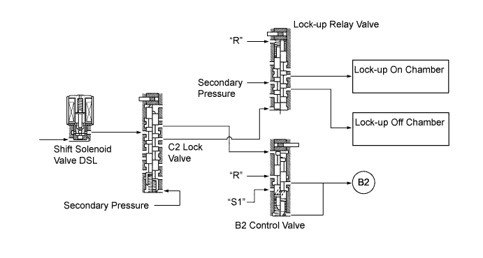
Shift solenoid valve DSL controls the B2 control valve via the C2 lock valve when the transaxle is shifted in R or S1 range. During lock-up, the lock-up relay valve is controlled via the C2 lock valve.
-
-
ATF Temperature Sensor
-
The ATF temperature sensor is installed in the lower valve body for direct detection of the fluid temperature.
-
The ATF temperature sensor is used for correction of clutch and brake pressure to ensure smooth shift quality every time.
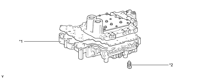
Text in Illustration *1 Lower Valve Body *2 ATF Temperature Sensor
-
-
Speed Sensor NT and Speed Sensor NC
-
This automatic transaxle uses a speed sensor NT and a speed sensor NC. Thus, the ECM can detect the timing of the shifting of the gears and appropriately control the engine torque and hydraulic pressure in response to various conditions.
-
The speed sensor NT detects the input speed of the transaxle. The direct clutch (C2) drum is used as the timing rotor for this sensor.
-
The speed sensor NC detects the speed of the counter gear. The counter drive gear is used as a timing rotor for this sensor.
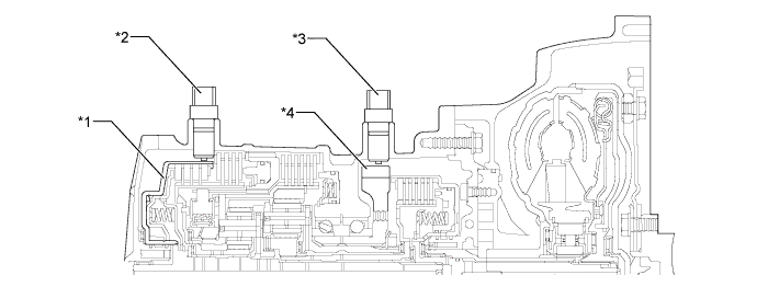
Text in Illustration *1 Direct Clutch Drum *2 Speed Sensor NT *3 Speed Sensor NC *4 Counter Drive Gear
-
-
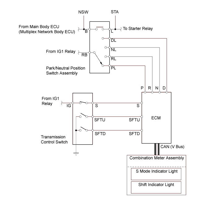
Transmission Control Switch and Park/Neutral Position Switch Assembly
-
The ECM uses these switches to detect the shift lever position.
-
The park/neutral position switch assembly sends the P, R, N and D position signals to the ECM. The ECM transmits signals to the combination meter assembly for the shift position indicator lights (P, R, N and D) in response to the signals received from the switch.
-
The transmission control switch is installed inside the lower shift lever assembly to inform the ECM of the shift lever position.
-
Switch terminal S is used to detect whether the shift lever is in D or S, and terminals SFTU and SFTD are used to detect the operation of the shift lever (if it is moved to "+" (forwards) or "-" (backwards) when S mode is selected. By transmitting signals to the ECM, the transmission control switch turns on both the shift indicator light and the S mode indicator light when the shift lever is moved to S, and indicates the selected range through shift indicator light.
-
-
-
OPERATION
-
Transmission Power Flow
-
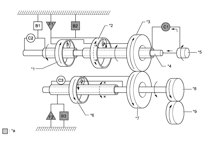
1st Gear (Shift Lever in D or S4, S3 and S2 Ranges)
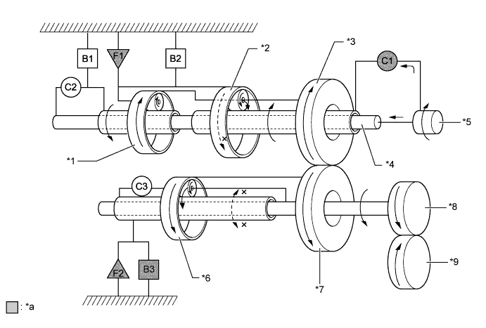
Text in Illustration *1 Rear Planetary Gear Unit *2 Front Planetary Gear Unit *3 Counter Drive Gear *4 Intermediate Shaft *5 Input Shaft *6 Underdrive Planetary Gear Unit *7 Counter Driven Gear *8 Differential Drive Pinion *9 Front Differential Ring Gear - - *a Operates - - -
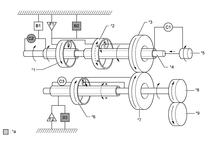
2nd Gear (Shift Lever in D or S4, S3 and S2 Ranges)
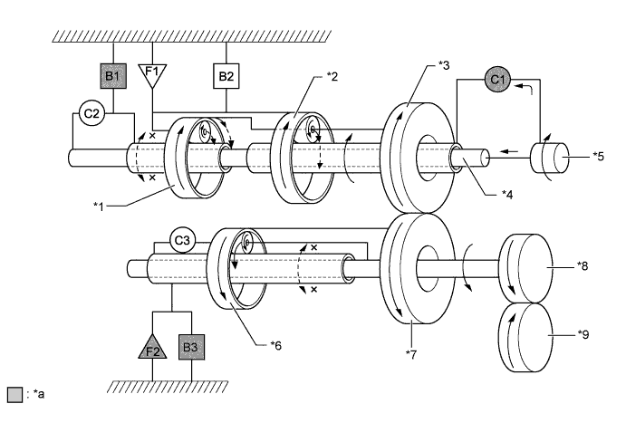
Text in Illustration *1 Rear Planetary Gear Unit *2 Front Planetary Gear Unit *3 Counter Drive Gear *4 Intermediate Shaft *5 Input Shaft *6 Underdrive Planetary Gear Unit *7 Counter Driven Gear *8 Differential Drive Pinion *9 Front Differential Ring Gear - - *a Operates - - -
3rd Gear (Shift Lever in D or S4 and S3 Ranges)
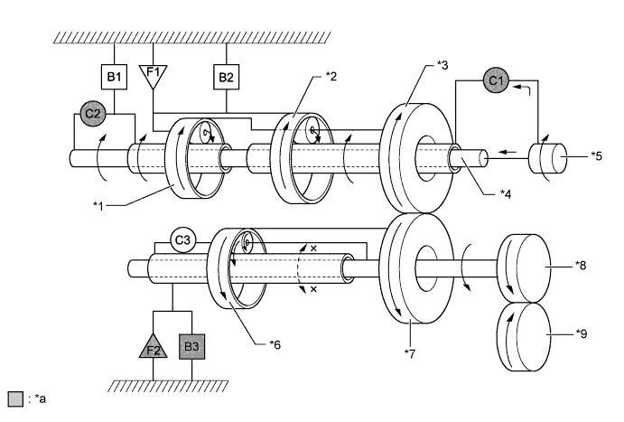
Text in Illustration *1 Rear Planetary Gear Unit *2 Front Planetary Gear Unit *3 Counter Drive Gear *4 Intermediate Shaft *5 Input Shaft *6 Underdrive Planetary Gear Unit *7 Counter Driven Gear *8 Differential Drive Pinion *9 Front Differential Ring Gear - - *a Operates - - -
4th Gear (Shift Lever in D or S4 Range)
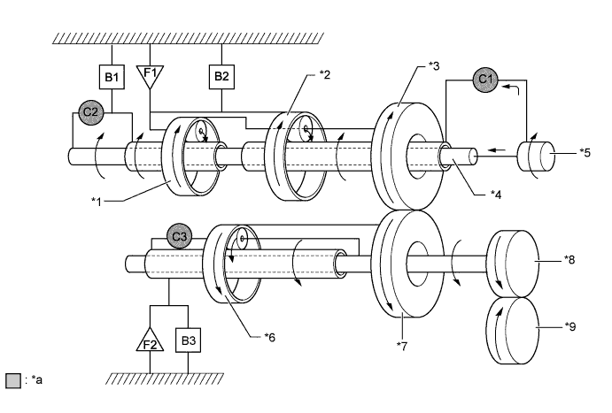
Text in Illustration *1 Rear Planetary Gear Unit *2 Front Planetary Gear Unit *3 Counter Drive Gear *4 Intermediate Shaft *5 Input Shaft *6 Underdrive Planetary Gear Unit *7 Counter Driven Gear *8 Differential Drive Pinion *9 Front Differential Ring Gear - - *a Operates - - -
1st Gear (Shift Lever in S1 Range)
Text in Illustration *1 Rear Planetary Gear Unit *2 Front Planetary Gear Unit *3 Counter Drive Gear *4 Intermediate Shaft *5 Input Shaft *6 Underdrive Planetary Gear Unit *7 Counter Driven Gear *8 Differential Drive Pinion *9 Front Differential Ring Gear - - *a Operates - - -
Reverse Gear (Shift Lever in R)
Text in Illustration *1 Rear Planetary Gear Unit *2 Front Planetary Gear Unit *3 Counter Drive Gear *4 Intermediate Shaft *5 Input Shaft *6 Underdrive Planetary Gear Unit *7 Counter Driven Gear *8 Differential Drive Pinion *9 Front Differential Ring Gear - - *a Operates - -
-
-
-
FAIL-SAFE
This fail-safe function minimizes the loss of operability when an abnormality occurs in a sensor or shift solenoid valve. For details, refer to the Repair Manual.
-
DIAGNOSIS
-
When the ECM detects a malfunction, the ECM records the malfunction and memorizes the information related to the fault. Furthermore, the ECM illuminates or blinks the Malfunction Indicator Lamp (MIL) in the combination meter assembly to inform the driver.
-
The ECM will also store the Diagnostic Trouble Codes (DTCs) of the malfunctions. The DTCs stored in the ECM are output to an intelligent tester via the ECM and the DLC3. For details, refer to the Repair Manual.
Tech Tips
To clear a DTC that is stored in the ECM, use an intelligent tester and disconnect the cable from the battery terminal for 1 minute or longer.
-