CRUISE CONTROL SYSTEM DETAILS
-
FUNCTION OF MAIN COMPONENTS
-
The main components in the cruise control system have the following functions:
Component Function Cruise Control Switch ON-OFF Button Turns the cruise control system on and off. CANCEL Switch A cancel signal is output to the ECM when this switch is operated. +RES Switch The accelerate function and resuming of a preset speed can be performed by operating this switch. A signal is output to the ECM when this switch is operated. -SET Switch The decelerate function and vehicle speed setting signals are output to the ECM when this switch is operated. ECM Controls all functions of the cruise control system in accordance with the signals from switches, sensors and ECUs. TCM* Performs downshifts and upshifts according to signals from the ECM. Brake Actuator Assembly Skid Control ECU Transmits the VSC operation signal to the ECM. Combination Meter Assembly Cruise Control Indicator Light
-
Based on a cruise control indicator operation signal sent by the ECM, the combination meter assembly illuminates the cruise control indicator light when the cruise control system has been turned on using the ON-OFF button on the cruise control switch.
-
Based on a cruise control indicator operation signal sent by the ECM, the combination meter assembly turns off the cruise control indicator light if a malfunction occurs in the cruise control system.
Cruise Control SET Indicator Light Illuminates while the cruise control system is controlling vehicle speed. Multi-information Display Displays a warning message to alert the driver in accordance with a signal provided by the ECM. Throttle Body with Motor Assembly Throttle Control Motor Adjusts the throttle valve opening angle in accordance with signals from the ECM. Throttle Position Sensor Detects the throttle valve opening angle and outputs it to the ECM. Accelerator Pedal Sensor Assembly Detects the accelerator pedal depression degree and outputs it to the ECM. Park/Neutral Position Switch Assembly Detects the shift lever position and transmits signals to the ECM. Lower Shift Lever Assembly Transmission Control Switch
-
Detects the shift lever position and transmits signals to the ECM.
-
Informs the ECM of driver upshift or downshift operations in S mode.
Stop Light Switch Assembly Detects when the brake pedal is depressed and transmits a signal to the ECM. VSC OFF Switch Detects the VSC OFF signal and outputs it to the skid control ECU.
-
*: Models with 2GR-FE engine
-
-
-
FUNCTION
-
The cruise control system has the following control functions.
Function Outline Constant Speed Control The ECM compares the actual vehicle speed and the set speed and if the vehicle speed is lower than the set speed, it uses the throttle control motor to increase the throttle valve opening angle. Set Control
-
When this system fulfils the following conditions, and the cruise control switch is moved to the -SET side and released, the ECM stores the vehicle speed and maintains the vehicle constantly at that speed.
-
The cruise control system has been turned on using the ON-OFF button on the cruise control switch.
-
The vehicle is being driven at a speed of approximately 40 km/h (25 mph) or more.
Low Speed Limit Control The low speed limit is the lowest speed that cruise control can be set at and it is designed to be approximately 40 km/h (25 mph). The cruise control system cannot be set below that speed. If the vehicle speed drops below that speed while the cruise control system is set and working to maintain vehicle speed, speed control by the cruise control system will be canceled automatically. However the set speed is kept in memory. COAST Switch Control
-
When the cruise control switch is held to the -SET side, the vehicle speed and the set vehicle speed change as follows:
-
The vehicle will decelerate.
-
The set vehicle speed will change to the speed at which the vehicle is being driven when the COAST switch (-SET side operation) is released.
Tap Down Control
-
When the cruise control switch is moved momentarily (approximately 0.6 seconds or less) to the -SET side, the vehicle speed and the set vehicle speed change as follows:
-
The vehicle will decelerate in increments of approximately 1 km/h (1 mph) each time the switch is moved.
-
However, if the difference between the actual vehicle speed and the set vehicle speed is greater than 5 km/h (3 mph), the set vehicle speed will change to the speed at which the vehicle is being driven when the switch is pushed.
ACC Switch Control
-
When the cruise control switch is held to the +RES side, the vehicle speed and the set vehicle speed change as follows:
-
The vehicle will accelerate.
-
The set vehicle speed will change to the speed at which the vehicle is being driven when the switch is released.
Tap Up Control
-
When the cruise control switch is moved momentarily (approximately 0.6 seconds or less) to the +RES side, the vehicle speed and the set vehicle speed change as follows:
-
The vehicle will accelerate in increments of approximately 1 km/h (1 mph) each time the switch is moved.
-
However, if the difference between the actual vehicle speed and the set vehicle speed is greater than 5 km/h (3 mph), the set vehicle speed will not change.
RES Switch Control If the vehicle speed is above the low speed limit, the cruise control resumes operation (when the cruise control switch is subsequently pushed to the +RES side) to reach the vehicle speed that was set at the time the driver canceled cruise control. Manual Cancel Control
-
If any of the following signals are sent to the ECM, cruise control speed control operation is canceled accordingly.
-
Shift lever is moved from D or S to any other position.
-
When 1st, 2nd or 3rd range is selected in S mode.
-
Stop light switch assembly on signal (The brake pedal is depressed.)
-
CANCEL switch on signal sent to the ECM (cruise control switch is moved to CANCEL side).
-
Cruise control switch (ON-OFF button) off signal sent to the ECM.
Automatic Cancel Control
-
If any of the following conditions occur while the cruise control system is controlling vehicle speed, the speed that is set in memory is cleared and speed control by the cruise control system is canceled.
-
Stop light switch assembly open or short circuit
-
Vehicle speed signals are abnormal.
Furthermore, the cruise control indicator light will turn off and a message indicating a malfunction will be displayed on the multi-information display until the cruise control system is turned off using the cruise control switch, and speed control by the cruise control system is disabled until the cruise control system is turned on again using the ON-OFF button.
-
If the following condition occurs while the cruise control system is controlling vehicle speed, the speed that is set in memory is cleared and speed control by the cruise control system is canceled.
-
ETCS-i malfunction
Furthermore, speed control by the cruise control system is disabled until the cruise control system is turned on again using the ON-OFF button.
-
If any of the following conditions occur while the cruise control system is controlling vehicle speed, the speed that is set in memory is cleared and speed control by the cruise control system is canceled.
-
Stop light switch assembly input signal is abnormal
-
Cancel circuit malfunction
Furthermore, the cruise control indicator light will turn off and a message indicating a malfunction will be displayed on the multi-information display until the cruise control system is turned off using the cruise control switch, and speed control by the cruise control system is disabled until the ignition switch is turned off.
-
If the following condition occurs while the cruise control system is controlling vehicle speed, the speed that is set in memory is cleared and speed control by the cruise control system is canceled.
-
Vehicle speed decreases by 16 km/h (10 mph) or more below the speed at which the cruise control is set.
-
If the following condition occurs while the cruise control system is controlling vehicle speed, speed control by the cruise control system is canceled.
-
Vehicle speed decreases below the low speed limit (approximately 40 km/h [25 mph]).
Shift-down Control When the vehicle is traveling uphill using cruise control, automatic transmission control may cause the transmission to shift down. During shift-down control, when the end of uphill travel is determined based on the throttle valve angle, the transmission will shift up after a certain period of time. When the transmission shifts down during ACC switch control or RES switch control, the transmission will shift up after ACC switch control or RES switch control ends. Other Cancelation Conditions
-
TR(A)C operates for a certain period of time during cruise control driving.
-
VSC operation.
-
-
-
CONSTRUCTION
-
Cruise Control Switch
-
The cruise control switch consists of the ON-OFF button and the +RES, -SET and CANCEL switches. The +RES, -SET and CANCEL switches are operated by moving the lever in the 3 directions indicated.
-
The cruise control switch is an automatic reset (normally open) type that turns on only when the switch is being operated and turns off as soon as the driver releases the switch. Furthermore, the functions of the switches are active only when the cruise control system has been turned on using the ON-OFF button on the cruise control switch.
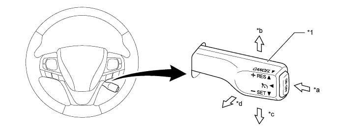
Text in Illustration *1 Cruise Control Switch - - *a ON-OFF Button *b +RES Switch *c -SET Switch *d CANCEL Switch
-
-
-
OPERATION
-
Combination Meter Assembly
-
The combination meter assembly provides a cruise control indicator light, cruise control SET indicator light and multi-information display to indicate the condition of the cruise control system.
Condition Cruise Control Indicator Light/ Cruise Control Set Indicator Light/ Multi-information Display*1 Set Standby 
Being Controlled*2 

System Malfunction 
Tech Tips
*1: These illustrations are examples.
*2: While driving at a set speed of 100 km/h (62 mph).
-
-
-
DIAGNOSIS
-
If a malfunction occurs in the cruise control system during cruise control operation, the ECM automatically cancels control and turns off both the cruise control indicator light and the cruise control SET indicator light. At this time, "Check Cruise Control System" is displayed on the multi-information display. The ECM stores the malfunction in the form of a 5-digit Diagnostic Trouble Code (DTC).
-
The 5-digit DTC can be read by connecting the Global TechStream (GTS) to the DLC3. For details, refer to the Repair Manual.
-