EMISSION CONTROL SYSTEM DETAILS
-
FUNCTION OF MAIN COMPONENTS
-
The main components of the 1AZ-FE emission control system are as follows:
Component Function TWC Oxidizes CO and HC in the exhaust gas and deoxidizes NOx at the same time, to purify them into CO2, H2O and N2. Air Fuel Ratio Sensor Is used to determine the concentration of oxygen remaining in the exhaust gas. Has a characteristic where its output is proportional to the engine air fuel ratio. Located upstream of the catalytic converter. For details Click here.
Oxygen Sensor The signal of the air fuel ratio sensor changes abruptly between lean and rich at the stoichiometric air fuel ratio. Located downstream of the catalytic converter. For details Click here.
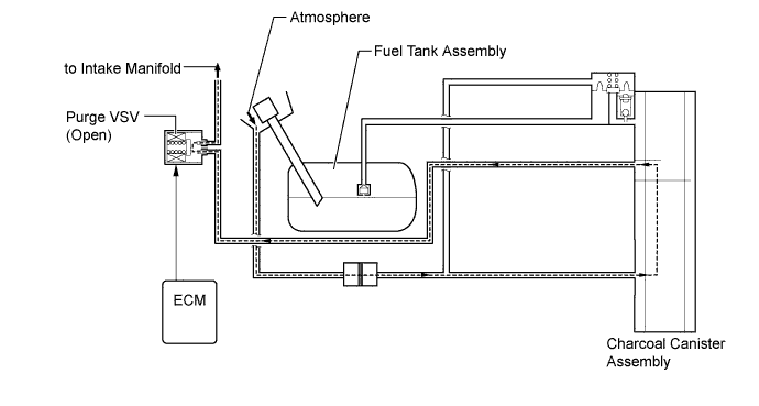
ECM Controls the volume of fuel consumed based primarily on the signal from the air fuel ratio sensor, with minor corrections based on the signal from the oxygen sensor. This control optimizes the exhaust emissions. Charcoal Canister Assembly Contains activated charcoal to absorb the fuel vapor that is created in the fuel tank assembly. Fresh Air Line Fresh air goes into the charcoal canister assembly and the cleaned drain air goes out into the atmosphere. Purge VSV Opens in accordance with the signals from the ECM when the system is purging, in order to send the fuel vapor that was absorbed by the charcoal canister assembly into the intake manifold. In system monitoring mode, this valve controls the introduction of vacuum into the fuel tank assembly. Canister Filter Prevents dust and debris in the fresh air from entering the system.
-
-
SYSTEM CONTROL
-
Purge Flow Control
-
When the engine has reached predetermined state (closed loop, engine coolant temperature above 80°C (176°F), etc.), stored fuel vapor is purged from the charcoal canister assembly whenever the purge VSV is opened by the ECM.
-
The ECM will change the duty ratio cycle of the purge VSV, thus controlling purge flow volume. Purge flow volume is determined by intake manifold pressure and the duty ratio cycle of the purge VSV. Atmospheric pressure is allowed into the charcoal canister assembly to ensure that purge flow is constantly maintained whenever purge vacuum is applied to the charcoal canister assembly.
-
-
-
CONSTRUCTION
-
Three-Way Catalytic Converter (TWC)
-
TWCs are provided in the exhaust manifold sub-assembly and also in the front exhaust pipe assembly.
-
An exhaust manifold with an integrated TWC is used for warm-up of the TWC in the front exhaust pipe assembly.
-
An ultra thin-wall, high-cell density, ceramic type TWC is used for the exhaust manifold sub-assembly and a thin-wall, ceramic type TWC is used for the front exhaust pipe assembly.
-
The ultra thin-wall TWC enables improved exhaust emissions by optimizing the cell density and the wall thickness.
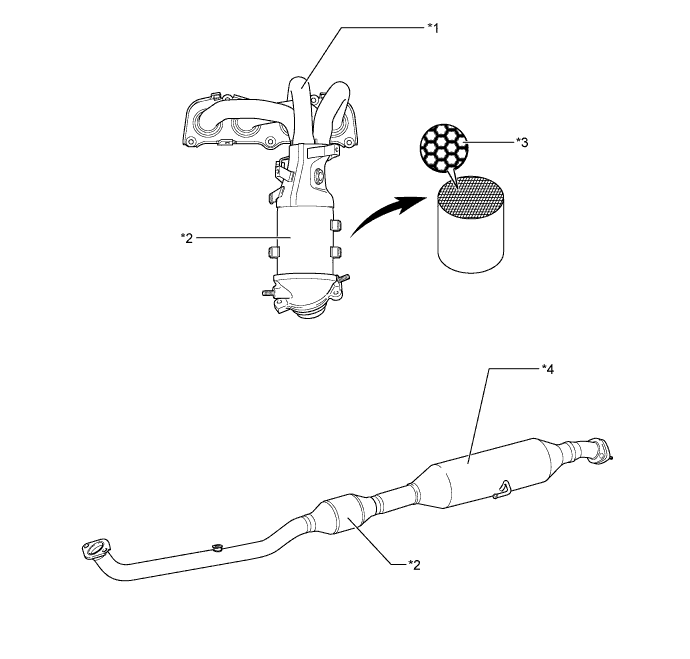
Text in Illustration *1 Exhaust Manifold Sub-assembly *2 TWC *3 Ultra Thin-wall *4 Front Exhaust Pipe Assembly
-
-
Fuel Inlet (Fresh Air Inlet)
-
The fresh air line inlet is located near the fuel inlet pipe opening. The fresh air from the atmosphere and drain air cleaned by the charcoal canister assembly will go in or out of the system through the passages shown below.
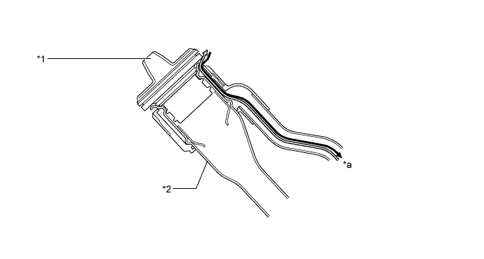
Text in Illustration *1 Fuel Tank Cap *2 Fuel Inlet Pipe *a To Charcoal Canister Assembly - - 
Fresh Air 
Cleaned Drain Air
-
-