ENGINE UNIT DETAILS
-
CONSTRUCTION
-
Cylinder Head Cover Sub-assembly
-
A lightweight aluminum alloy die-cast cylinder head cover sub-assembly is used.
-
The cylinder head cover gasket and the spark plug gasket are integrated to reduce the number of parts.
-
Acrylic rubber, which excels in heat resistance and reliability, is used for the cylinder head cover gasket.
-
The shape of the Positive Crankcase Ventilation (PCV) baffle plate has been optimized to enhance ventilation volume.
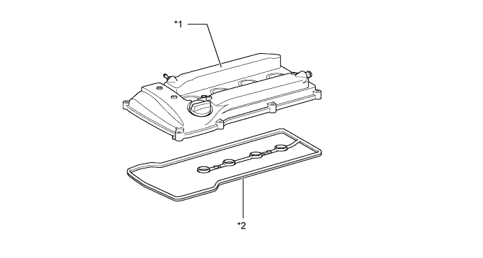
Text in Illustration *1 Cylinder Head Cover Sub-assembly *2 Cylinder Head Cover Gasket
-
-
Cylinder Head Gasket
-
A steel-laminate type cylinder head gasket is used. A shim is used around the cylinder bore of the gasket to help enhance sealing performance and durability.
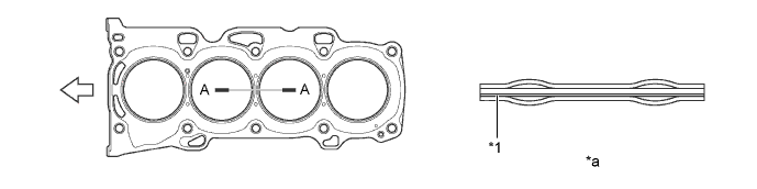
Text in Illustration *1 Shim - - *a A-A Cross Section - - 
Engine Front - -
-
-
Cylinder Head Sub-assembly
-
The cylinder head sub-assembly, which is made of aluminum, has a pentroof-type combustion chamber. The spark plugs are located in the center of the combustion chamber in order to improve the engine anti-knocking performance.
-
Through the adoption of taper squish combustion chambers, the engine knocking resistance is improved and fuel efficiency is ensured.
-
Upright intake ports are used to improve intake efficiency.
-
Installing the injectors in the cylinder head enables the injectors to inject fuel as close as possible to the combustion chamber. This prevents the fuel from adhering to the intake port walls, which reduces HC exhaust emissions.
-
The routing of the water jacket in the cylinder head sub-assembly is optimized to ensure cooling performance. In addition, a water bypass passage is provided below the exhaust ports to reduce the number of parts and achieve weight reduction.
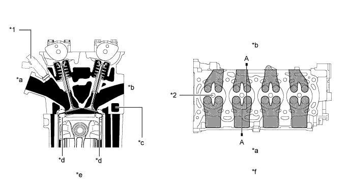
Text in Illustration *1 Fuel Injector Assembly *2 Spark Plug Hole *a Intake Side *b Exhaust Side *c Bypass Passage *d Taper Squish Area *e A-A Cross Section *f View from Bottom Side
-
-
Cylinder Block Sub-assembly
-
The cylinder block sub-assembly is made of aluminum alloy, so it is lightweight.
-
Producing the thin cast-iron liners and aluminum alloy cylinder block sub-assembly as a unit realizes a compact design. The liner is thin, and reboring is not possible.
-
The air conditioning compressor brackets are integrated with the cylinder block sub-assembly and stiffening crankcase assembly.
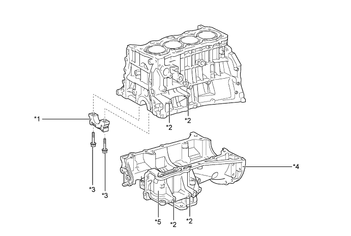
Text in Illustration *1 Crankshaft Bearing Cap *2 Air Conditioning Compressor Bracket *3 Crankshaft Bearing Cap Set Bolt (Plastic Region Tightening Bolt) *4 Stiffening Crankcase Assembly *5 Oil Filter Bracket - - -
Air passage holes are provided in the bulkhead of the cylinder block sub-assembly. As a result, the air at the bottom of the cylinders flows smoother, and pumping losses (back pressure at the bottom of the piston generated by the piston's reciprocating movement) is reduced to improve the engine's output.
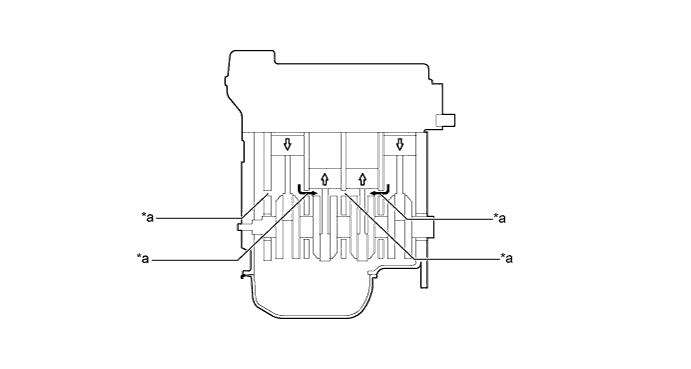
Text in Illustration *a Air Passage Hole - - 
Air Flow Piston's Movement -
The liners are a spiny-type, which have been manufactured so that their cast outers form large irregular surfaces in order to enhance the adhesion between the liners and the aluminum cylinder block sub-assembly. The enhanced adhesion helps heat dissipation, resulting in a lower overall temperature and reduced heat deformation of the cylinder bores.
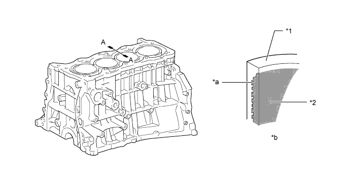
Text in Illustration *1 Cylinder Block Sub-assembly *2 Liner *a Irregularly Shaped Outer Cast Surface of Liner *b A-A Cross Section -
Cylinder block water jacket spacers are provided in the water jacket of the cylinder block sub-assembly.
-
The cylinder block water jacket spacers suppress the coolant flow in the center of the water jackets, guide the coolant above and below the cylinder bores water jacket to ensure uniform temperature distribution. As a result, the viscosity of the engine oil that acts as a lubricant between the bore walls and the pistons can be lowered, thus reducing friction.
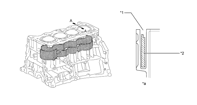
Text in Illustration *1 Water Jacket *2 Cylinder Block Water Jacket Spacer *a A-A Cross Section - -
-
-
Piston
-
The pistons are made of aluminum alloy.
-
The tops of the pistons utilize a taper squish shape to achieve fuel combustion efficiency.
-
The piston skirts are coated with resin to reduce friction losses.
-
Full-floating piston pins are used.
-
By increasing the machining precision of the cylinder bore diameter in the block, only one size piston is required.
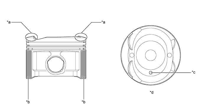
Text in Illustration *a Taper Squish Shape *b Resin Coating *c Front Mark *d View from the Top
-
-
Connecting Rod Sub-assembly
-
The connecting rod sub-assemblies and connecting rod caps are made of high-strength steel for weight reduction.
-
Knock pins are used at the mating surfaces of the connecting rod caps to minimize the shifting of the connecting rod caps during assembly.
-
Nutless-type connecting rod bolts (plastic region tightening bolts) are used for a lighter design.
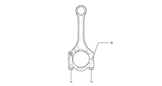
Text in Illustration *1 Plastic Region Bolt *2 Knock Pin
-
-
Crankshaft
-
The crankshaft has 5 journals and 8 balance weights.
-
The crankshaft is made of forged steel.
-
The surface roughness of the pins and journals has been reduced to reduce friction.
-
The balance shaft drive gear is installed onto the crankshaft.
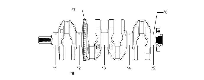
Text in Illustration *1 No. 1 Main Bearing Journal *2 No. 2 Main Bearing Journal *3 No. 3 Main Bearing Journal *4 No. 4 Main Bearing Journal *5 No. 5 Main Bearing Journal *6 Balance Weight *7 Balance Shaft Drive Gear *8 Oil Hole
-
-
Crankshaft Bearing
-
The crankshaft bearing groove is shallower at the ends of the bearing than in the middle. This reduces the total friction of the oil pump by reducing the oil leakage at the ends of the bearing.
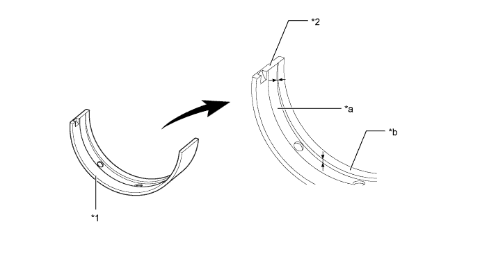
Text in Illustration *1 Crankshaft Bearing *2 Bearing Edge *a Crankshaft Bearing Groove *b Bearing Center
-
-
Balance Shaft
-
Balance shafts are used to reduce vibration.
-
A direct-drive gear that is installed on the crankshaft also acts as a counterweight.
-
In addition, a resin gear is used on the driven side to suppress noise and offer a lightweight design.
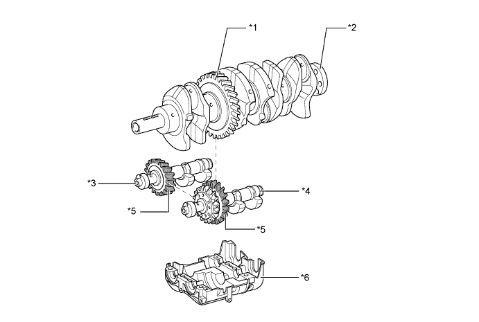
Text in Illustration *1 Balance Shaft Drive Gear *2 Crankshaft *3 No. 2 Balance Shaft *4 No. 1 Balance Shaft *5 Resin Gear *6 Balance Shaft Housing
-
-
Crankshaft Pulley
-
The rigidity of the crankshaft pulley with its built-in torsional damper rubber reduces noise.
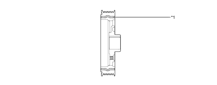
Text in Illustration *1 Torsional Damper Rubber - -
-
-
Valve Mechanism
-
The valve mechanism uses a Variable Valve Timing-intelligent (VVT-i) system to achieve lower fuel consumption and higher engine performance, and to reduce exhaust emissions. For details, Click here.
-
Each cylinder is equipped with 2 intake valves and 2 exhaust valves. Intake and exhaust efficiency is increased due to larger total port areas.
-
The valves are directly opened and closed by 2 camshafts.
-
The camshaft and No. 2 camshaft are driven by a timing chain.
-
Along with increase in the amount of valve lift, a shimless type valve lifter is used. This valve lifter raises the cam contact surface.
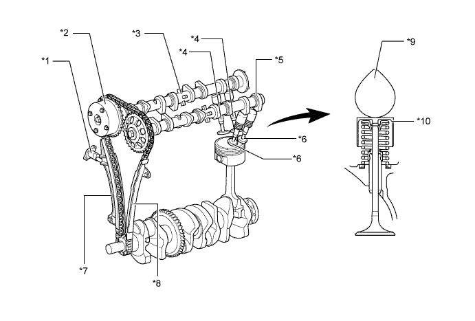
Text in Illustration *1 No. 1 Chain Tensioner Assembly *2 Camshaft Timing Gear Assembly *3 Camshaft *4 Intake Valves *5 No. 2 Camshaft *6 Exhaust Valves *7 Chain Tensioner Slipper *8 No. 1 Chain Vibration Damper *9 Cam *10 Valve Lifter Tech Tips
The adjustment of the valve clearance is accomplished by selecting and replacing the appropriate valve lifters. A total of 35 valve lifters are available in 0.020 mm (0.0008 in.) increments, from 5.060 mm (0.199 in.) to 5.740 mm (0.226 in.). For details, refer to the Repair Manual.
-
-
Valve Timing
Intake camshaft Open 3° to 43° BTDC Close 60° to 20° ABDC Exhaust camshaft Open 45° BBDC Close 3° ATDC 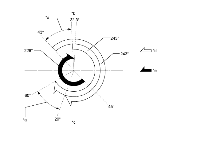
Text in Illustration *a VVT-i Operation Range *b TDC *c BDC *d Intake Valve Opening Angle *e Exhaust Valve Opening Angle - - -
Camshaft
-
The camshaft (intake) is provided with a timing rotor to trigger the camshaft position sensor.
-
Oil passages are provided in the camshaft (intake) in order to supply engine oil pressure to the VVT-i system.
-
A camshaft timing gear assembly is installed on the front of the camshaft to vary the timing of the intake valves.
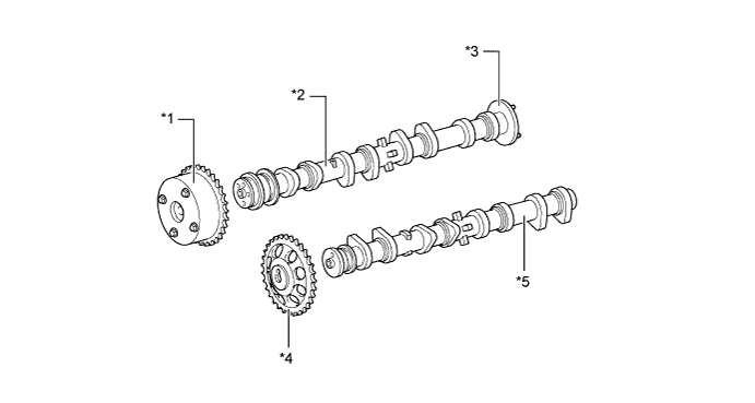
Text in Illustration *1 Camshaft Timing Gear Assembly *2 Camshaft *3 Timing Rotor *4 No. 2 Camshaft Timing Sprocket *5 No. 2 Camshaft - -
-
-
Camshaft Timing Gear Assembly
-
The camshaft timing gear assembly consists of an outer housing that is driven by the timing chain sprocket, and a vane sub-assembly that is coupled to intake camshaft.
-
The oil pressure sent from the advance or retard side passage of the intake camshaft causes rotation of the camshaft timing gear vane relative to the timing chain sprocket to vary the valve timing continuously (steplessly).
-
When the engine stops, the camshaft timing gear assembly is locked to the most retarded angle by its lock pin. This ensures engine startability.
-
When hydraulic pressure is not applied to the camshaft timing gear assembly immediately after the engine has been started, the lock pin locks the movement of the camshaft timing gear assembly to prevent a knocking noise.
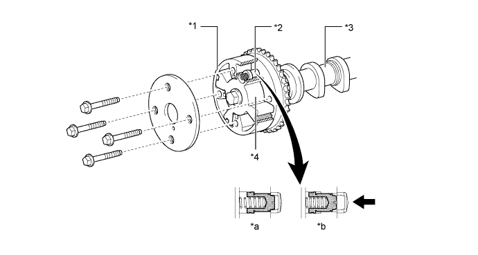
Text in Illustration *1 Outer Housing *2 Lock Pin *3 Camshaft (Intake Camshaft) *4 Vane (Fixed on Intake Camshaft) *a Engine Stopped *b Engine Operating Oil Pressure - -
-
-
Chain Sub-assembly, No. 2 Chain Sub-assembly and No. 1 Chain Tensioner Assembly
-
Roller type chains with a pitch of 8.0 mm (0.315 in.) are used to make the engine more compact.
-
The chains are lubricated by an oil jet.
-
The No. 1 chain tensioner assembly uses a spring and oil pressure to maintain proper chain tension at all times. The No. 1 chain tensioner assembly suppresses noise generated by the chain sub-assembly.
-
The No. 1 chain tensioner assembly is a ratchet type with a non-return mechanism.
-
To achieve excellent serviceability, the No. 1 chain tensioner assembly is constructed so that it can be removed and installed from the outside of the timing chain cover sub-assembly.
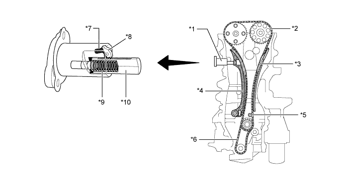
Text in Illustration *1 No. 1 Chain Tensioner Assembly *2 Chain Sub-assembly *3 No. 1 Chain Vibration Damper *4 Chain Tensioner Slipper *5 Oil Jet *6 No. 2 Chain Sub-assembly *7 Cam Spring *8 Cam *9 Spring *10 Plunger
-
-
Engine Mount
-
Liquid-filled compound engine mounts are used for the front, right and left engine mounts to realize low noise and vibration and to achieve high levels of both ride comfort and driveability.
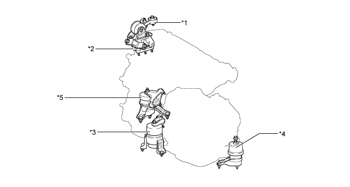
Text in Illustration *1 Torque Rod *2 Torque Rod Bracket *3 Front Engine Mount (Liquid-filled Compound Engine Mount) *4 Left Engine Mount (Liquid-filled Compound Engine Mount) *5 Right Engine Mount (Liquid-filled Compound Engine Mount) - -
-
-
V-ribbed Belt
-
Accessory components are driven by a serpentine belt consisting of a single V-ribbed belt. It reduces the overall engine length, weight and number of engine parts.
-
The V-ribbed belt tensioner assembly eliminates the need for tension adjustment.
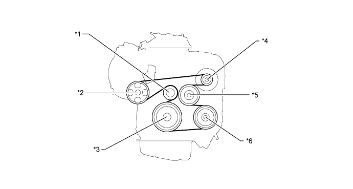
Text in Illustration *1 V-ribbed Belt Tensioner Assembly *2 Idler Pulley *3 Crankshaft Pulley *4 Generator Pulley *5 Water Pump Pulley *6 Air Conditioning Compressor Pulley
-
-
V-ribbed Belt Tensioner Assembly
-
The V-ribbed belt tensioner assembly consists of an idler pulley, an arm, and a spring. The idler pulley maintains belt tension using the force of the spring.
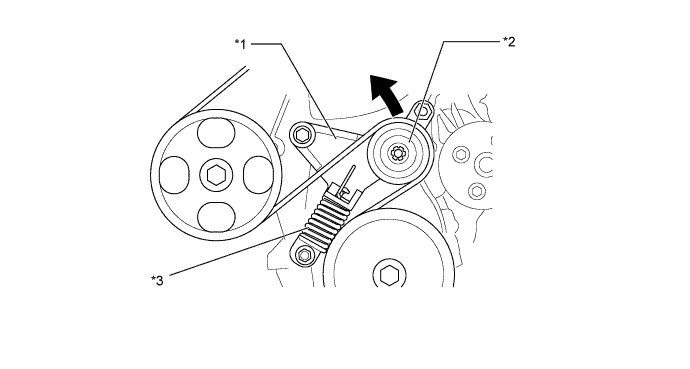
Text in Illustration *1 Arm *2 Idler Pulley *3 Spring - -
-
-