BODY STRUCTURE DETAILS
-
FUNCTION
-
Impact Absorbing Structure for Frontal Collision
-
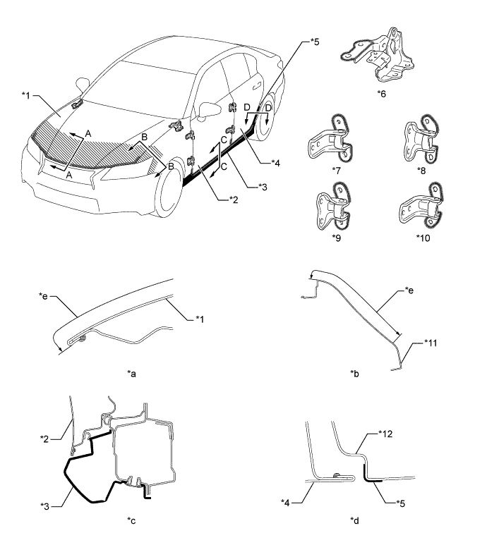
A structure that ensures collision energy absorption efficiency, dissipates impact, and minimizes cabin deformation during a frontal collision has been achieved.
-
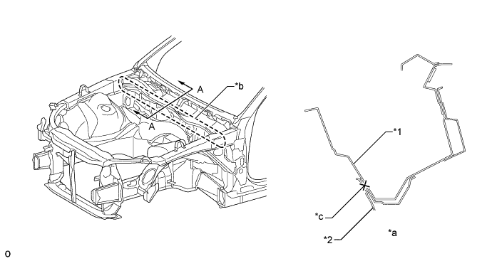
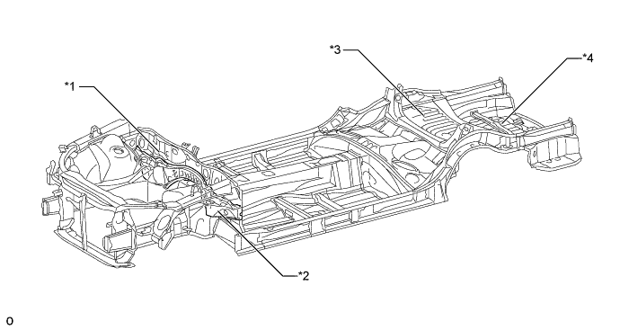
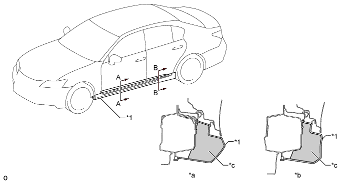
Ultra high-tensile strength sheet steel (980 MPa class) is used for the No. 1 rocker panel reinforcement. In addition, strengthening reinforcement is added in the No. 1 rocker panel reinforcement. As a result, deformation of the cabin, which is caused by the vehicle's pitching in an offset front collision, has been suppressed.
-
The rocker front end portion (outer rocker extension) is protruded forward to receive collision load input from the tires in an offset front collision and to absorb the impact, thus suppressing body deformation on the periphery of the cabin.
-
The lower front body pillar reinforcement and outer front body pillar reinforcement are constructed with an overlap structure that features upper-and-lower separation together to strengthen the front body pillar portion, thus suppressing body deformation (caused by collision load input from the tires in an offset front collision) on the periphery of the cabin.
-
High-tensile strength sheet steel (590 MPa class) is used for the front door inside panel reinforcement. In addition, the longitudinal wall of the front door inside panel reinforcement is located further toward the interior side than the centroid, thus suppressing deformation of the door by compression load in an offset front collision.
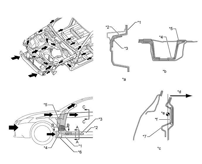
Text in Illustration *1 Inner Fender Panel *2 No. 1 Rocker Panel Reinforcement *3 No. 4 Rocker Panel Reinforcement *4 Outer Front Body Pillar Extension *5 Lower Front Body Pillar Reinforcement *6 Outer Rocker Extension *7 Front Door Inside Panel Reinforcement - - *a A - A Cross Section *b B - B Cross Section *c C - C Cross Section *d Interior Side *e Centroid *f Longitudinal Wall 
Front Impact Energy - - -
-
-
Impact Absorbing Structure for Side Collision
-
A structure that ensures collision energy absorption efficiency, dissipates impact, and minimizes cabin deformation during a side collision has been achieved.
-
Hot-stamped steel (1500 MPa class), ultra high-tensile strength sheet steel (980 MPa class) and high-tensile strength sheet steel (590 MPa class) are used for each body frame part, thus ensuring strength against side collisions and achieving weight reduction and structure simplicity.
Tech Tips
Hot-stamped steel is a highly strengthened material, which is made by forming and cooling heated steel simultaneously and then hardening it.
-
Hot-stamped steel (1500 MPa class) is used for the upper center body pillar reinforcement. In addition, the high-tensile strength sheet steel (590 MPa class) center pillar upper hinge reinforcement is located inside the upper center body pillar reinforcement.
-
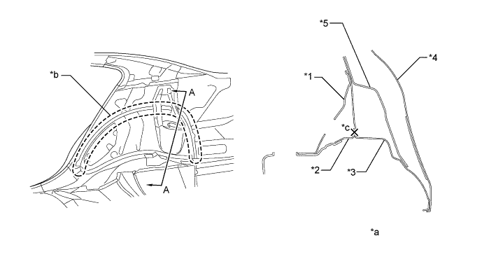
Hot-stamped steel (1500 MPa class) is used for the roof side rail.
-
High-tensile strength sheet steel (590 MPa class) is used for the center roof panel reinforcement.
-
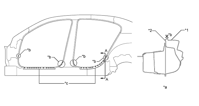
Ultra high-tensile strength sheet steel (980 MPa class) is used for the No. 1 rocker panel reinforcement, and high-tensile strength sheet steel (590 MPa class) is used for the outer rocker panel and No. 3 rocker panel reinforcement, which are inside the No. 1 rocker panel reinforcement. Front-and-rear length has been increased to suppress corruption of the rocker cross-section in a side collision, thus reducing the center body pillar's intrusion into the cabin.
-
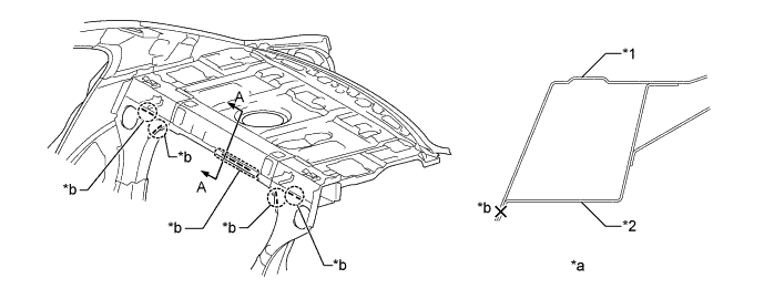
The thickness of the rear door side impact protection beam has been increased, thus reducing the rear door's intrusion into the cabin in a side collision.
-
A bulkhead (No. 6 rocker panel reinforcement) is added to the No. 5 rocker panel reinforcement. In addition, hard resin reinforcement (inner rear rocker panel protector) is located in the interior side to transfer the rear door side impact protection beam and load, thus suppressing the intrusion of the rear door in a side collision.
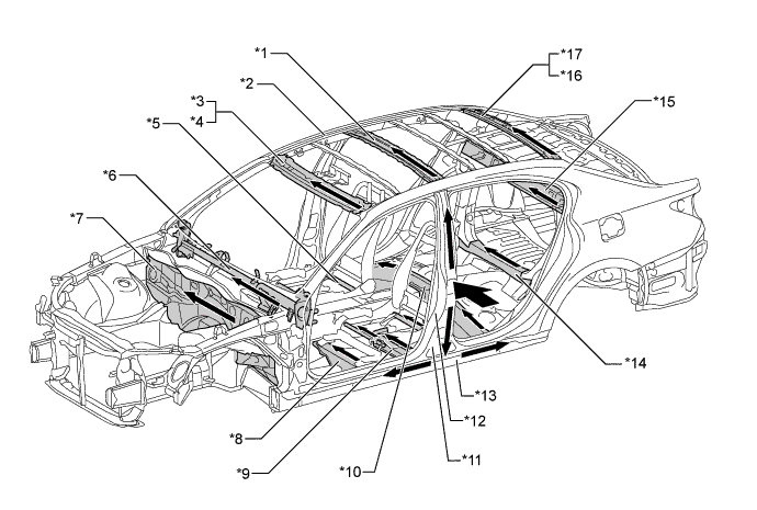
Text in Illustration *1 Center Roof Panel Reinforcement *2 Roof Side Rail *3 Outer Windshield Header Panel *4 Inner Windshield Header Panel *5 Connecting Rod *6 Instrument Panel Reinforcement Assembly *7 Dash Panel Sub-assembly *8 Front Floor Cross Member Sub-assembly *9 Front Floor Cross Side Member *10 Center Floor Cross Member *11 Upper Center Body Pillar Reinforcement *12 Center Pillar Upper Hinge Reinforcement *13 No. 1 Rocker Panel Reinforcement *14 Rear Center Floor Cross Member Sub-assembly *15 Room Partition Panel Sub-assembly *16 Upper Inner Back Window Frame *17 Back Window Frame - - Side Impact Energy - - 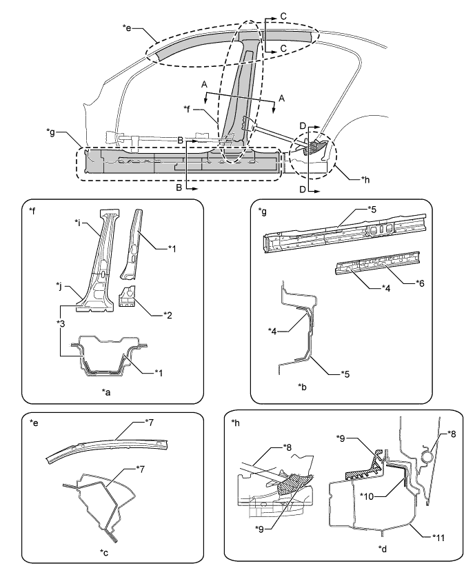
Text in Illustration *1 Center Pillar Upper Hinge Reinforcement *2 No. 1 Center Pillar Lower Hinge Reinforcement *3 Upper Center Body Pillar Reinforcement *4 Outer Rocker Panel *5 No. 1 Rocker Panel Reinforcement *6 No. 3 Rocker Panel Reinforcement *7 Roof Side Rail *8 Rear Door Side Impact Protection Beam *9 Inner Rear Rocker Panel Protector *10 No. 6 Rocker Panel Reinforcement *11 No. 5 Rocker Panel Reinforcement - - *a A - A Cross Section *b B - B Cross Section *c C - C Cross Section *d D - D Cross Section *e Roof Side Rail Portion *f Center Body Pillar Portion *g Rocker Portion *h Rear Rocker Portion *i Hot-stamped Steel *j High-tensile Strength Steel
-
Collision load input from the center body pillar in a side collision is transferred either to the ECU bracket installed on the center front floor panel tunnel sub-assembly or its upper portion through the front floor cross member reinforcement sub-assembly, separate type front seat cushion pad and connecting rod. As a result, the diffusion of collision load has been optimized to reduce the deformation amount of the body in a side collision.
-
The center roof panel reinforcement (high-tensile strength steel (590 MPa class)) and No. 2 roof panel reinforcement bracket are located on the upper portion of the center pillar on models with normal roof, to suppress the amount of side rail intrusion by transferring and scattering the load to the side opposite to the collision, thus aiming for a reduction in the amount of body deformation in a side collision.
-
A front door stiffener cushion is provided inside the door panel to enhance the transmission efficiency of collision load, thus aiming for a reduction of the injury criterion level.
-
The lower front door trim pad is provided in the front door trim board sub-assembly to reduce collision load toward the passengers in a side collision, thus aiming for a reduction of the injury criterion level.
-
The position, shape and rigidity of the front door trim board sub-assembly shoulder portion and the front door armrest assembly have been optimized to reduce collision load toward the driver and front passengers in a side collision, thus aiming for a reduction of the injury criterion level.
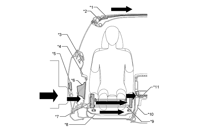
Text in Illustration *1 Center Roof Panel Reinforcement *2 No. 2 Roof Panel Reinforcement Bracket *3 Front Door Trim Board Sub-assembly *4 Front Door Armrest Assembly *5 Front Door Stiffener Cushion *6 Lower Front Door Trim Pad *7 Separate Type Front Seat Cushion Pad *8 Front Floor Cross Member Reinforcement Sub-assembly *9 Connecting Rod *10 Center Front Floor Panel Tunnel Sub-assembly *11 ECU Bracket - - Side Impact Energy - - -
-
-
Lessening Pedestrian Head Injury
-
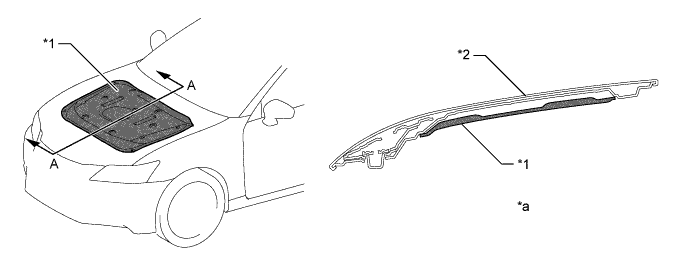
In the case of a collision with a pedestrian, pedestrian injury reduction is taken into consideration by the use of pedestrian injury reduction body. An impact absorbing body structure is used on the periphery of the hood panel and cowl top panel, thus achieving a body structure which reduces impact to the pedestrian's head, etc.
-
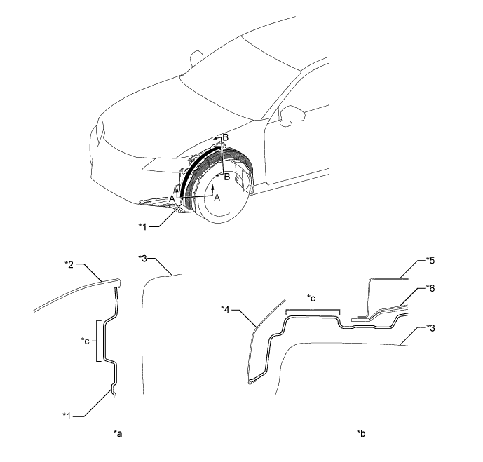
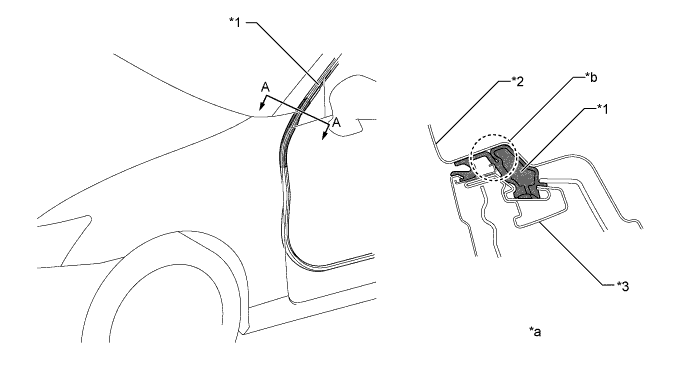
A structure which is easily bent is used for the upper front fender protector. If a pedestrian's head, etc. collides with the hood sub-assembly, the upper front fender protector bends to reduce opposed reaction force from the hood sub-assembly to the head etc., thus aiming for a reduction of impact against a pedestrian.
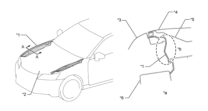
Text in Illustration *1 Upper Front Fender Protector *2 Hood Sub-assembly *3 Front Fender Panel *4 Hood Panel *5 Inner Hood Panel *6 Upper Front Apron to Cowl Side Member *a A - A Cross Section *b Structure which can be Easily Bent
-
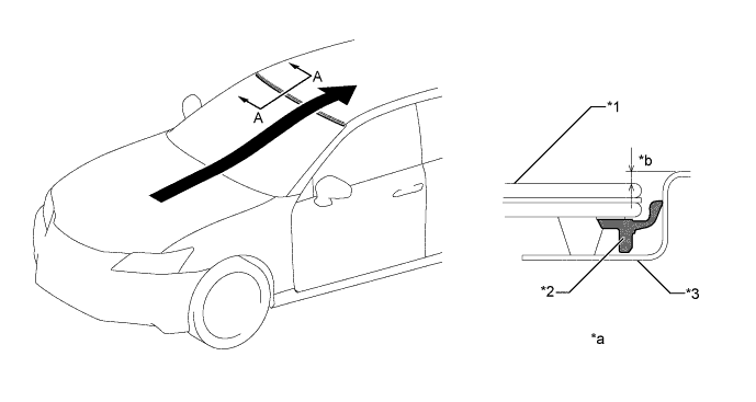
A vertical bead structure is used for the inner hood panel, thus aiming for a reduction of impact against the pedestrian's head, etc. in a collision with a pedestrian. In addition, the height and pitch of the beads have been optimized, thus achieving a slim hood sub-assembly structure while maintaining impact reduction performance.
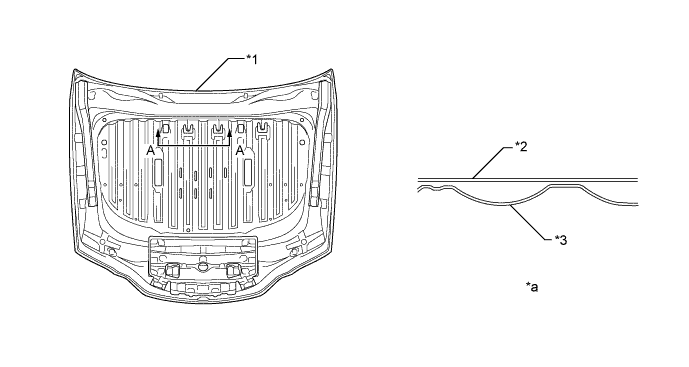
Text in Illustration *1 Hood Sub-assembly *2 Hood Panel *3 Inner Hood Panel - - *a A - A Cross Section - -
-
Bead shapes which can form bending base points are provided at the end of the inner hood panel. As a result, the structure bends to deform easily at base points created by the ledge end of the inner hood panel and the beads next to the hood lock hook base when the pedestrian's thigh area collides with the hood end, thus aiming for a reduction of impact against the pedestrian's thigh area.
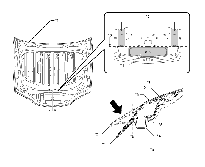
Text in Illustration *1 Inner Hood Panel *2 Hood Panel Reinforcement *3 Hood Panel *4 Hood Lock Hook *5 Hood Lock Hook Base - - *a A - A Cross Section *b Fold Line *c Bead *d Ledge *e Before Collision *f After Impact Absorption Impact - -
-
For the hood hinge assembly, a crushable structure is used for the hood hinge outer bracket plate to achieve a construction which can be crushed easily. As a result, reduction of the impact against a pedestrian has been aimed for in a collision with a pedestrian.
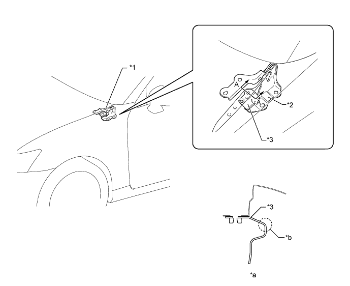
Text in Illustration *1 Hood Hinge Assembly *2 Hood Hinge Bracket *3 Hood Hinge Outer Bracket Plate - - *a A - A Cross Section *b Crushable Structure
-
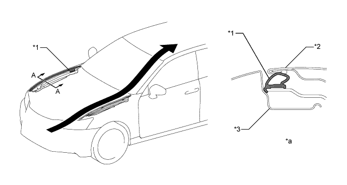
The following shape is used for the cowl top ventilator louver sub-assembly, thus maintaining necessary rigidity and aiming for a reduction of impact against a pedestrian in a collision with a pedestrian.
-
The line of the hood to cowl top seal has been made flat and smooth, thus achieving a structure which can deform easily.
-
Both sides of the cowl top ventilator louver sub-assembly have been made open, thus achieving a structure which can deform easily.
-
A thin-walled portion is provided to control deformation by creating deformation points.
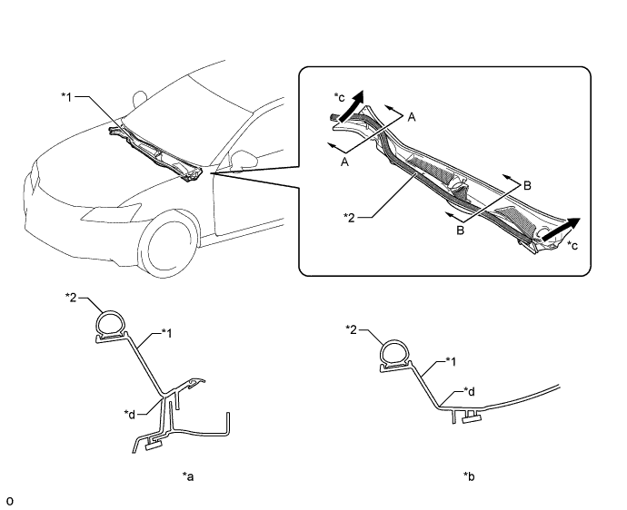
Text in Illustration *1 Cowl Top Ventilator Louver Sub-assembly *2 Hood to Cowl Top Seal *a A - A Cross Section *b B - B Cross Section *c Open Structure *d Thin-walled Portion (Deformation Point)
-
By providing fold points on the front outer cowl top panel and by making the structure easily crushable, energy coming from the expected direction in a head area collision is more effectively absorbed, and a structure which reduces the remaining areas which are not completely crushed has been achieved. As a result, impact against the head area, etc. is reduced in a collision with a pedestrian.
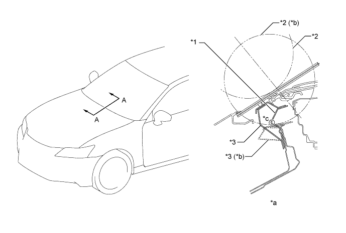
Text in Illustration *1 Front Outer Cowl Top Panel *2 Headform Impactor *3 No. 1 Wiper Motor Mounting Bracket - - *a A - A Cross Section *b After Collision *c Fold Point - - -
-
-
Lessening Pedestrian Leg Injury
-
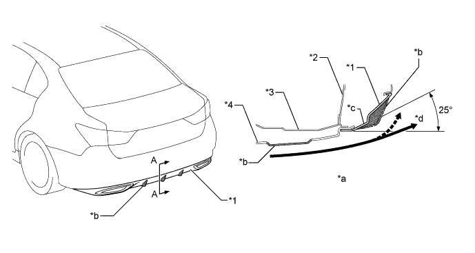
A pedestrian injury reduction body is used in consideration of reducing injury of a pedestrian in the case of a collision with a pedestrian. The impact absorbing structure is used on the periphery of the front bumper, thus achieving a body structure which reduce impact toward a pedestrian's leg, etc.
-
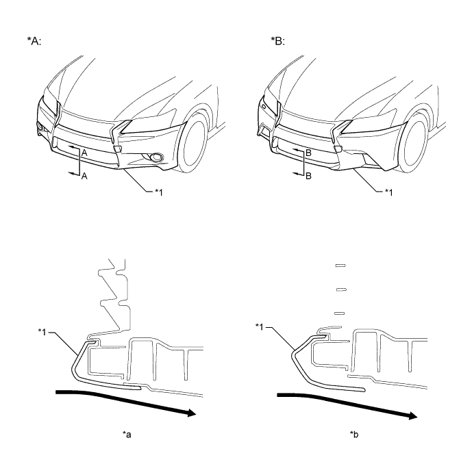
In the front bumper portion, collision load is absorbed in area A of the illustration in a collision with a pedestrian, thus reducing impact against the pedestrian's leg. Also, impact toward the leg is transferred to the outside of the vehicle in area B of the illustration. In area A, a front bumper energy absorber (which is composed of a foaming agent to reduce impact load toward the knees) and a lower No.1 radiator grille (which uses a high energy absorption box structure that absorbs more energy more effectively than a rib structure in the energy absorbing material to support the knees) are positioned effectively as two types of impact absorbing materials, to simultaneously reduce impacts against the pedestrian's legs and to improve design performance.
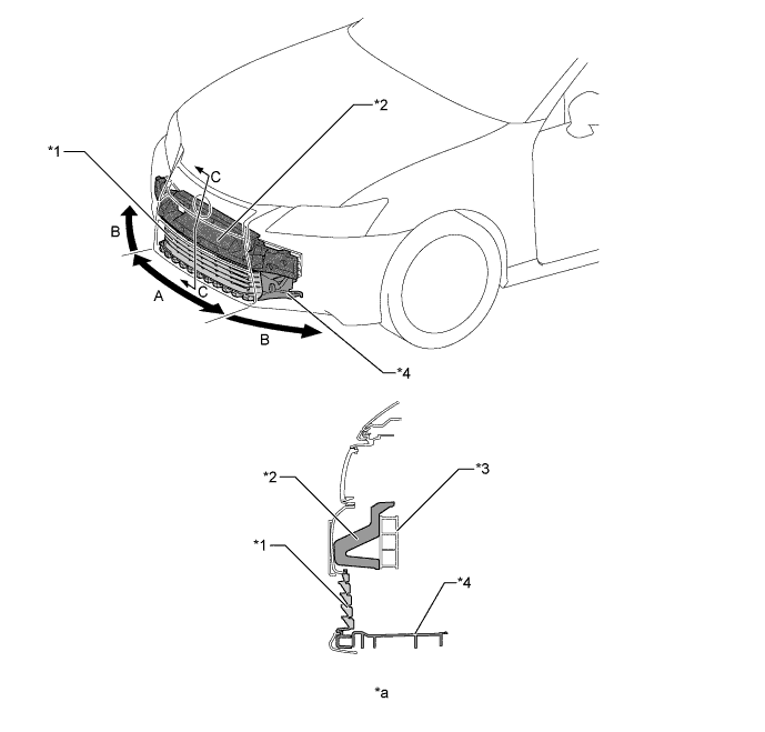
Text in Illustration *1 Lower No. 1 Radiator Grille *2 Front Bumper Energy Absorber *3 Front Bumper Reinforcement *4 Radiator Support Opening Cover *a C - C Cross Section - -
-
-
-
Aerodynamics
-
A step shape is used for the lower end of the front wheel opening extension pad, thus aiming for optimization of aerodynamic performance. The outer side step of the front wheel opening extension pad has been extended in its lower end position, thus suppressing the volume of air hitting against the rotating bodies of the tires. As a result, turbulence generated by the rotation of the front tires which disturbs airflow around the front tires has been suppressed, thus reducing air resistance and ensuring a high level of straight-line stability at a high speed by adjusting the airflow. In addition, the inner side step of the front wheel opening extension pad has been shortened in its lower end portion, thus aiming for prevention of the front wheel opening extension pad itself from causing air resistance.
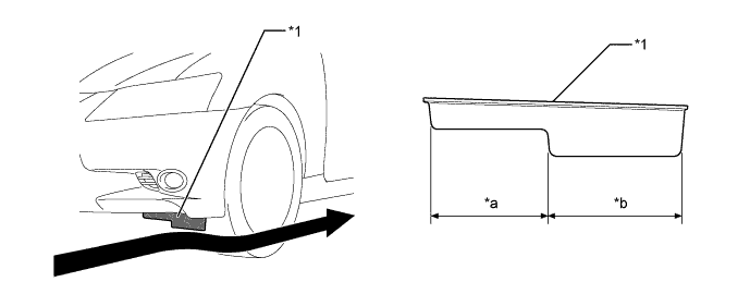
Text in Illustration *1 Front Wheel Opening Extension Pad - - *a Inner Side of Vehicle *b Outer Side of Vehicle Airflow - - -
A groove is provided in the front fender splash shield sub-assembly. As a result, airflow in the wheelhouse is introduced to smoothly flow parallel to the tires to make it flow in the wheelhouse smoothly, thus ensuring superior maneuver stability.
Text in Illustration *1 Front Fender Splash Shield Sub-assembly *2 Front Bumper Cover *3 Front Tire *4 Front Fender Panel *5 Upper Front Apron to Cowl Side Member *6 Front Spring Support *a A - A Cross Section *b B - B Cross Section *c Groove Structure - - 
Groove Structure Airflow -
The lower end of the front bumper cover has been set low to adjust the volume of air flowing to the under floor. As a result, lifting force has been suppressed, thus ensuring superior maneuver stability.
Text in Illustration *A Except F SPORT *B F SPORT *1 Front Bumper Cover - - *a A - A Cross Section *b B - B Cross Section Airflow - - -
A rear floor housing shield is provided, with the aim of suppressing the air volume hitting against the rotating bodies of the tires. As a result, turbulence generated by the rotation of the rear tires, which disturbs airflow around the rear tires has been suppressed, thus reducing air resistance and ensuring a high level of straight-line stability at a high speed by adjusting the airflow.
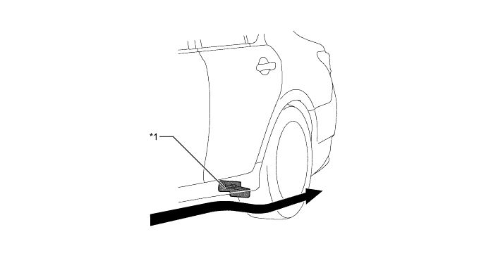
Text in Illustration *1 Rear Floor Housing Shield - - Airflow - - -
Beads are provided to free the high-pressure turbulence outward that causes air resistance in the rear wheelhouse by the rotation of the rear tires.
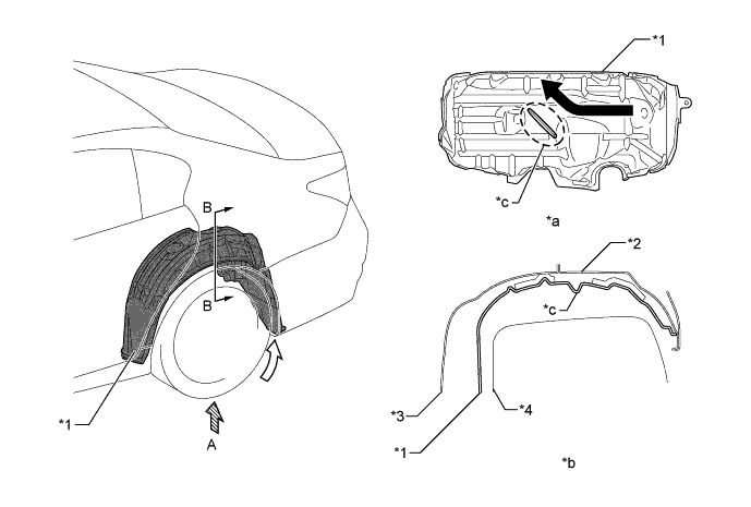
Text in Illustration *1 Rear Wheel House Liner *2 Outer Quarter Wheel House Panel *3 Inner Quarter Wheel House Panel *4 Rear Tire *a View from A *b B - B Cross Section *c Bead - - 
Airflow Caused by Tire Rotation Air Introduction by Bead -
The rear end portion of the luggage compartment door panel sub-assembly has been given a sharp shape, thus aiming for air resistance reduction by smoothly introducing airflow from the roof to the rear.
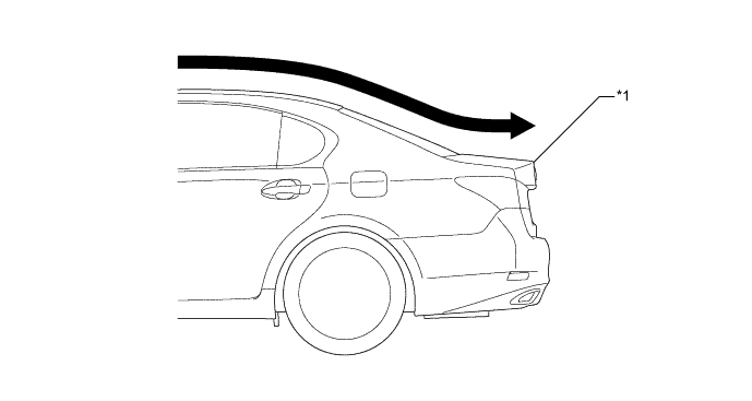
Text in Illustration *1 Luggage Compartment Door Panel Sub-assembly - - Airflow - - -
On models with rear spoiler sub-assembly, the rear spoiler sub-assembly suppresses rearward air vortices, thus aiming for air resistance reduction by smoothing the airflow.
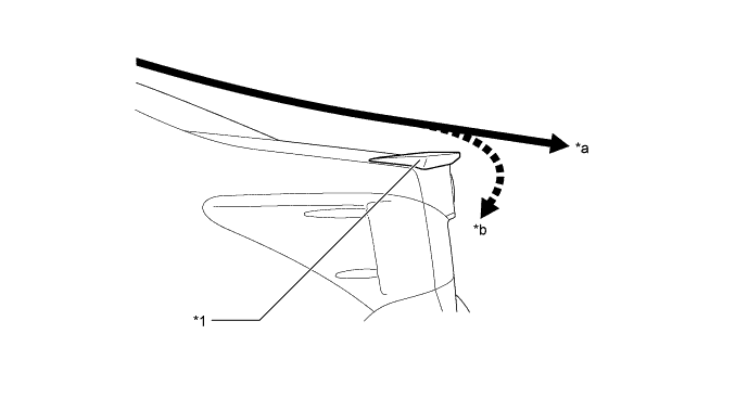
Text in Illustration *1 Rear Spoiler Sub-assembly - - *a Smooth Airflow *b Vortex -
An edge shape and an aero stabilizing fin are used for the rear combination lamp assembly. The edge portion cuts and blows airflow rearward to suppress vortices, thus aiming for air resistance reduction by the airflow adjustment effects which flow air smoothly. An edge shape and an aero stabilizing fin are used for the rear combination lamp assembly. The edge portion cuts and blows airflow rearward to suppress vortices, thus aiming for air resistance reduction by the airflow adjustment effects which flow air smoothly.
-
Aero stabilizing fins (vortex generators) are used for the rear combination light assembly. As air flows over the surfaces of a moving vehicle, friction can cause that air to tumble over and under itself, increasing drag and creating erratic air pressure forces around the vehicle. Aero stabilizing fins alter the airflow before it becomes turbulent, creating a series of controlled spins, or vortices, and helping to equalize air pressure forces, reduce drag and improve vehicle stability.
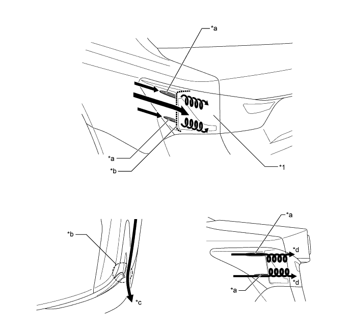
Text in Illustration *1 Rear Combination Light Assembly - - *a Aero Stabilizing Fin *b Edge Shape *c Cut and Blown Air *d Generated Vortices -
To create a smooth rearward airflow for the air which enters from the front to under floor, the following parts with airflow adjustment effects are located on the lower surface of the vehicle. Smooth airflow in the lower surface of the vehicle enhances the speed of airflow and a low pressure region is created between the vehicle and the road surface (Venturi effect). This low pressure region attracts the vehicle to the road surface, thus causing down force. Thus, superior straight-line stability has been achieved.
-
A flat airflow adjustment surface is provided for the engine under cover. Also, an aero stabilizing fin is provided.
-
The surface area of the front floor cover and the No. 1 rear floor board sub-assembly has been increased, and the height from the ground has also been optimized. In addition, an aero stabilizing fin is provided.
-
The under floor cutting angle of the No. 1 floor under cover has been optimized. In addition, an aero stabilizing fin is provided.
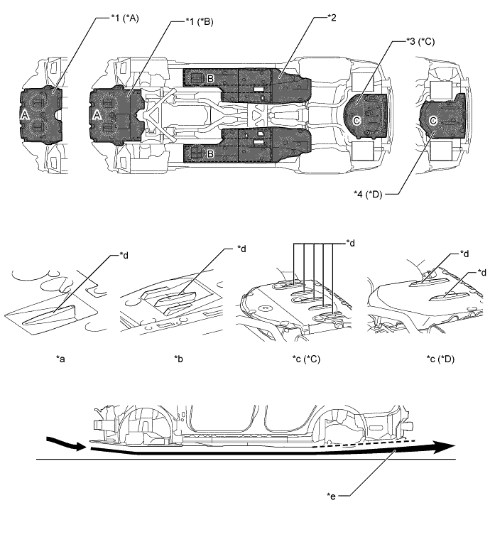
Text in Illustration *A AWD Models *B 2WD Models *C Models with Deep Rear Floor Pan *D Models with Shallow Rear Floor Pan *1 Engine Under Cover *2 Front Floor Cover *3 No. 1 Rear Floor Board Sub-assembly *4 No. 1 Floor Under Cover *a Section A *b Section B *c Section C *d Aero Stabilizing Fin *e Under Floor High-speed Airflow - - -
-
The general surface of the lower rear bumper cover is angled at 25 degrees, ensuring superior aerodynamic performance by flowing airflow from the under floor to the rear. In addition, the aero stabilizing fin of the lower rear bumper cover contributes to smooth airflow in conjunction with the aero stabilizing fin of the No. 1 floor under cover.
Text in Illustration *1 Lower Rear Bumper Cover *2 Body Lower Back Panel *3 Rear Floor Pan *4 No. 1 Floor Under Cover *a A - A Cross Section *b Aero Stabilizing Fin *c General Surface *d Smooth Airflow
-
-
-
CONSTRUCTION
-
Lightweight and Highly Rigid Body
-
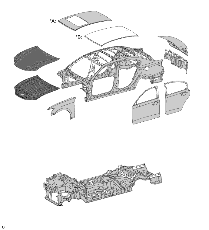
High-tensile strength steel, ultra high-tensile strength steel, hot-stamped steel and aluminum steel are used in order to achieve excellent body rigidity and a lightweight body.
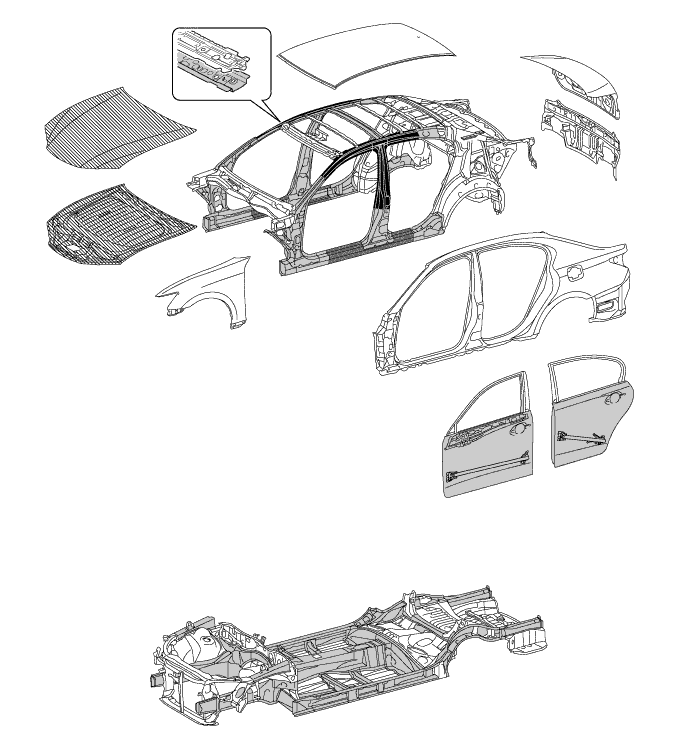
Text in Illustration Ultra High-tensile Strength Steel 
High-tensile Strength Steel 
Aluminum Steel 
Hot-stamped Steel -
Along with the use of high-tensile strength sheet steel for the inner windshield header panel, the back window frame and upper inner back window frame are structured with closed cross-sections, thus ensuring superior roof strength.
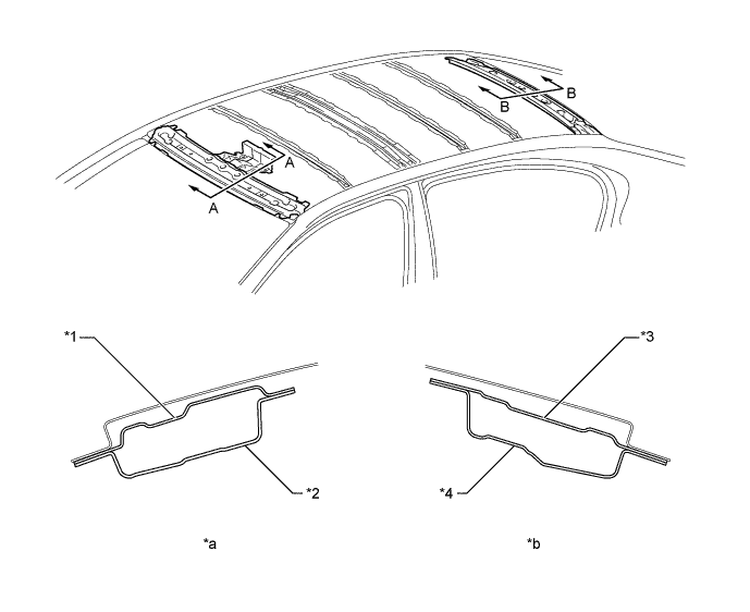
Text in Illustration *1 Outer Windshield Header Panel *2 Inner Windshield Header Panel *3 Upper Inner Back Window Frame *4 Back Window Frame *a A - A Cross Section *b B - B Cross Section -
An upper front pillar door opening gusset, which connects the apron member portion and the front pillar portion, is provided in the front fender portion. As a result, a superior steering feel and roll feeling are ensured. In addition, to avoid preventing collision safety, a bead shape is provided for a structure which is easily deformable in a collision.
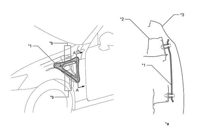
Text in Illustration *1 Upper Front Pillar Door Opening Gusset *2 Inner Cowl Top Side Panel *3 Front Fender Panel - - *a A - A Cross Section *b Bead -
Many spot welding points are provided on the dash panel and inner cowl top panel, thus ensuring superior maneuvering stability by enhancing the connecting rigidity of the panels.
Text in Illustration *1 Inner Cowl Top Panel *2 Dash Panel *a A - A Cross Section *b Spot Welding Point Increased Area *c Spot Welding Point - - -
Many spot welding points are provided in the wheelhouse portion, thus ensuring maneuvering stability (steering response, rear grip feeling) by enhancing the connecting rigidity of the panels.
Text in Illustration *1 No. 2 Rear Suspension Spring Support Reinforcement *2 Inner Quarter Wheelhouse Panel *3 Outer Quarter Wheelhouse Panel *4 Outer Side Panel *5 Outer Roof Side Panel - - *a A - A Cross Section *b Spot Welding Point Increased Area *c Spot Welding Point - - -
Laser welding is added in the door opening portion, thus enhancing the panel connecting performance between the spot welding areas to ensure superior vehicle response performance in the early stages of transitive steering (lane change, slalom) and response.
Text in Illustration *1 No. 5 Rocker Panel Reinforcement *2 Outer Side Panel *a A - A Cross Section *b Laser Welding *c Spot Welding Area - - -
Laser welding is added in the room partition opening portion, thus enhancing the panel connecting ability of the panels between the spot welding areas to ensure a superior vehicle response performance at the early stages of transitive steering (lane change, slalom) and gripping feel in the rear.
Text in Illustration *1 Outer Upper Back Rail *2 Upper Back Panel *a A - A Cross Section *b Laser Welding -
The No. 3 center floor reinforcement is located so as to connect the right and left of the front side installation portion of the rear suspension member sub-assembly in a straight line, thus ensuring a high level of rigidity at the load point. As a result, superior maneuvering stability has been achieved.
-
Spot welding points between the front center floor pan and center floor pan, the No. 2 center floor cross member and center floor pan and the No. 1 rear floor cross member and center floor pan are optimally positioned, thus achieving superior maneuvering stability.
-
The thickness of the center floor pan has been increased, thus achieving superior maneuvering stability, riding comfort and quietness.
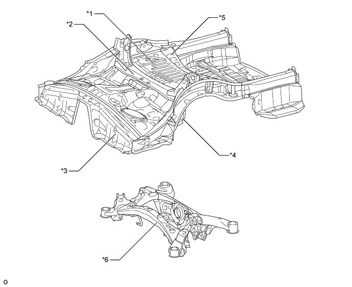
Text in Illustration *1 Center Floor Pan *2 No. 2 Center Floor Cross Member *3 Front Center Floor Pan *4 No. 3 Center Floor Reinforcement *5 No. 1 Rear Floor Cross Member *6 Rear Suspension Member Sub-assembly -
The shapes of the radiator support sub-assembly and rear under body have been optimized and each type of brace provided on the under floor has been optimally placed, thus ensuring superior maneuvering stability.
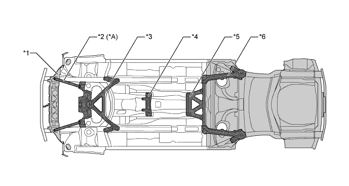
Text in Illustration *A 2WD Models - - *1 Radiator Support Sub-assembly *2 Upper No. 2 Front Suspension Member *3 Front Suspension Member Brace *4 Center Front Floor Brace Sub-assembly *5 Center Front Floor Brace *6 Rear Body Mounting Cushion Sub-assembly
-
-
Anti-corrosion Sheet Steel
-
Anti-corrosion sheet and aluminum steel are used as in the following illustration:
Text in Illustration *A Models with Sliding Roof *B Models with Normal Roof Aluminum Steel Anti-corrosion Sheet Steel
-
-
Anti-chipping Application and Rust-resistant Performance
-
Polyvinyl Chloride (PVC) coating is applied to the wheel housings, and other parts that are located where they are susceptible to stone chipping damage, improving the rust-resistance of these areas.
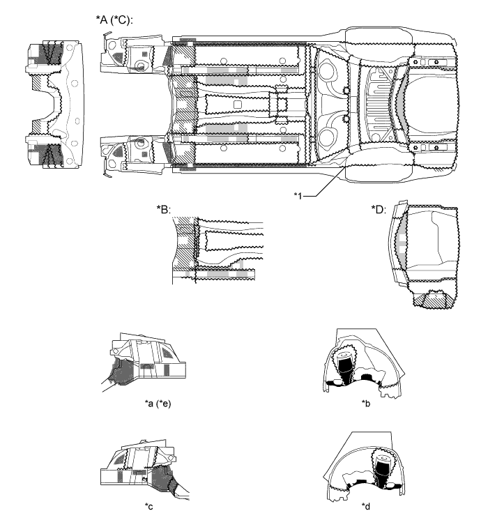
Text in Illustration *A 2WD Models *B AWD Models *C Models with Deep Rear Floor Pan *D Models with Shallow Rear Floor Pan *1 Edge Seal - - *a Front Right Hand Apron *b Rear Left Hand Wheelhouse *c Front Left Hand Apron *d Rear Right Hand Wheelhouse *e Edge seal is symmetrical with the left side of the front fender apron - - Under Coating Area (Heavy Portion) Under Coating Area (Heavy Portion (Wet)) Under Coating Area (General Portion (Wet)) Under Coating Area (General Portion) -
Chip resistant coating (soft anti-chipping primer) is applied to the leading edge of the hood to help prevent rust.
-
A large body rocker panel molding assembly and quarter panel protector (models for Europe and Australia) are used to protect the paint surface from icy snow or gravel and to achieve a high level of rust resistance.
-
Wax is applied to the edge of the hood panel, door lower portion, door hinge assembly and hood hinge assembly to improve rust-resistant performance.
Text in Illustration *1 Hood Panel *2 Font Door Panel *3 Body Rocker Panel Molding Assembly *4 Rear Door Panel *5 Quarter Panel Protector *6 Hood Hinge Assembly *7 Upper Front Door Hinge Assembly *8 Upper Rear Door Hinge Assembly *9 Lower Front Door Hinge Assembly *10 Lower Rear Door Hinge Assembly *11 Fender Panel *12 Side Outer Panel *a A - A Cross Section *b B - B Cross Section *c C - C Cross Section *d D - D Cross Section *e Soft Anti-chipping Primer Application Range - - Soft Anti-chipping Primer Wax
-
-
Sound Absorbing and Vibration Damping Materials
-
A hood insulator is provided on the rear of the hood sub-assembly. This achieves excellent sound insulation performance.
Text in Illustration *1 Hood Insulator *2 Hood Sub-assembly *a A - A Cross Section - - -
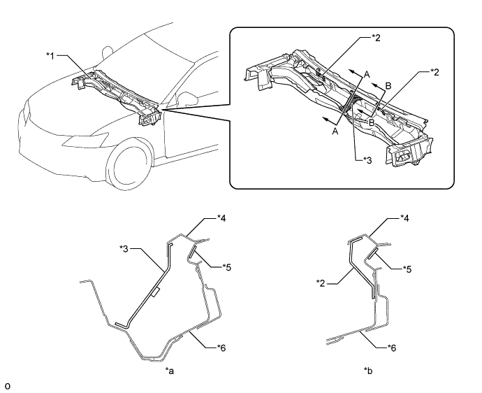
An insulator (No. 1 cowl top panel insulator, No. 2 cowl top panel insulator and cowl top panel insulator sheet) are provided for the front panel assembly, thus aiming for reduction of noise intruding from the engine compartment into the cabin.
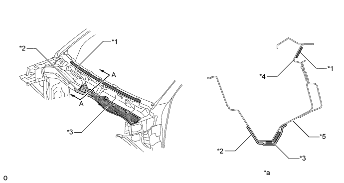
Text in Illustration *1 No. 2 Cowl Top Panel Insulator *2 No. 1 Cowl Top Panel Insulator *3 Cowl Top Insulator Sheet *4 Front Outer Cowl Top Panel *5 Inner Cowl Top Panel - - *a A - A Cross Section - - -
A dash panel insulator assembly is provided. This insulates and absorbs the engine noise to reduce the amount of engine noise leaking into the cabin.
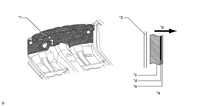
Text in Illustration *1 Dash Panel Insulator Assembly *2 Dash Panel *a Construction Material *b Interior Side *c Urethane *d Ethylene-propylene Diene Terpolymer (EPDM) *e Felt - - -
Sound absorbing material is provided on the side of the Tibia pad (dash panel insulator pad No. 2/dash panel insulator pad No. 3). This insulates and absorbs the engine noise to reduce the amount of engine noise leaking into the cabin.
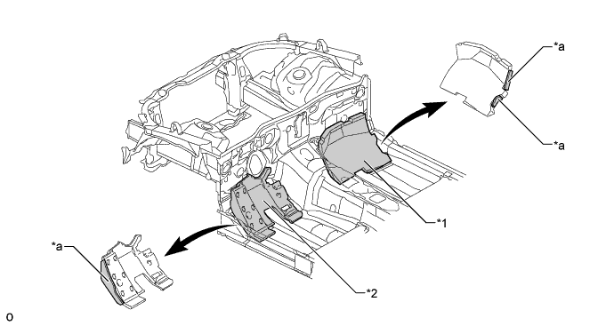
Text in Illustration *1 Dash Panel Insulator Pad No. 2 *2 Dash Panel Insulator Pad No. 3 *a Sound Absorbing Material - - -
An outer dash panel insulator is provided. This reduces the amount of engine noise leaking into and out of the cabin.
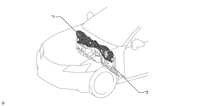
Text in Illustration *1 Outer Dash Panel Insulator *2 Dash Panel Sub-assembly -
Noise absorbing material is provided for the fender splash shield sub-assembly FR , thus reducing sound created by flying sand, flying water and road noise.
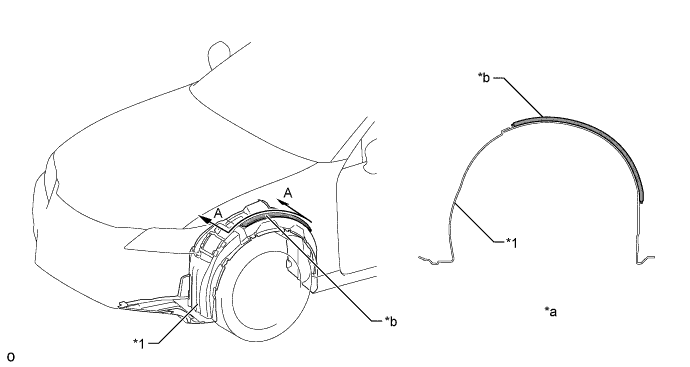
Text in Illustration *1 Fender Splash Shield Sub-assembly FR - - *a A - A Cross Section *b Noise Absorbing Material -
Noise absorbing material is provided for the rear wheelhouse liner, thus reducing sound created by flying sand, flying water and road noise.
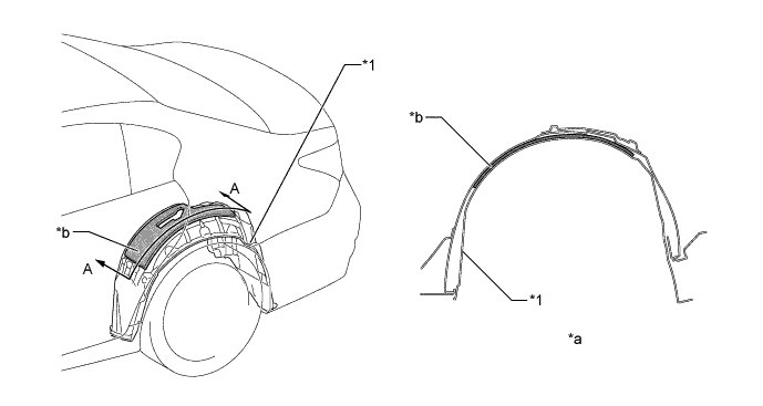
Text in Illustration *1 Rear Wheelhouse Liner - - *a A - A Cross Section *b Noise Absorbing Material -
By using the following structures, resonance tuning of the dash panel and floor pan has been implemented. As a result, superior Noise, Vibration, Harshness (NVH) performance is ensured.
-
A front side member to dash panel cross member is provided.
-
A dash panel to cowl brace is provided.
-
Dash sandwich sheet steel is provided, in which the dash panel insulator sheet and dash panel insulator sheet LH are sandwiched by the dash panel and rear dash panel in the driver seat side, and the dash panel insulator sheet RH is sandwiched by the dash panel and No. 2 dash panel in the front passenger side.
-
The bead shape and the location of the center floor pan and rear floor pan have been optimized.
-
The sheet thickness of the dash panel has been optimized.
-
The sheet thickness of the center floor pan has been optimized.
Text in Illustration *1 Dash Panel *2 Front Side Member to Dash Panel Cross Member *3 Center Floor Pan *4 Rear Floor Pan 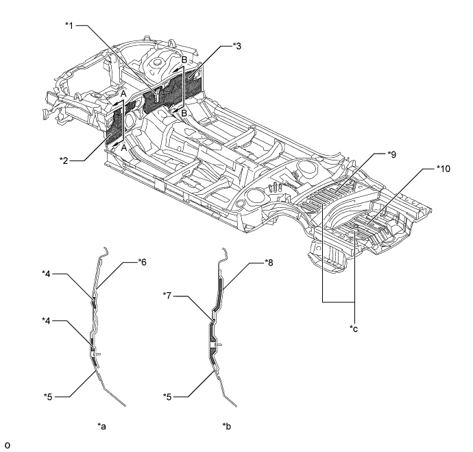
Text in Illustration *1 Dash Panel to Cowl Brace *2 No. 3 Dash Panel Insulator Assembly *3 No. 2 Dash Panel Insulator Assembly *4 Dash Panel Insulator Sheet LH *5 Dash Panel *6 Rear Dash Panel *7 Dash Panel Insulator Sheet RH *8 No. 2 Dash Panel *9 Center Floor Pan *10 Rear Floor Pan *a A - A Cross Section *b B - B Cross Section *c Bead - - -
-
The holding parts of the front panel assembly (No. 1 inner cowl top to cowl brace and No. 1 wiper motor mounting bracket) are optimally structured and a damping material (No. 2 cowl top panel insulator) is used, thus aiming for suppression of muffled sounds caused by glass vibration.
Text in Illustration *1 Front Panel Assembly *2 No. 1 Inner Cowl Top to Cowl Brace *3 No. 1 Wiper Motor Mounting Bracket *4 Outer Cowl Top Panel *5 No. 2 Cowl Top Panel Insulator *6 Inner Cowl Top Panel *a A - A Cross Section *b B - B Cross Section -
The No. 4 upper back reinforcement is connected with the longitudinal wall of the upper back panel and the closed cross-section is used for the reinforcement, thus suppressing vibration of the upper back panel to reduce chatter sounds caused by the speakers and muffled sounds.
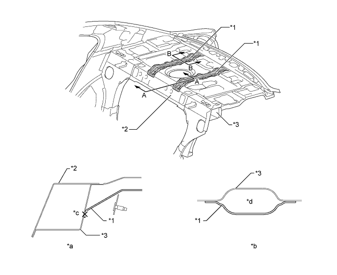
Text in Illustration *1 No. 4 Upper Back Reinforcement *2 Outer Upper Back Panel *3 Upper Back Panel - - *a A - A Cross Section *b B - B Cross Section *c Joint *d Closed Cross Section -
To reduce the amount of road noise, engine noise, and droning sound that enters the cabin, the floor panel is coated with a floor silencer.
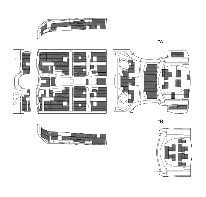
Text in Illustration (2WD and LHD Models) *A Models with Shallow Rear Floor Pan *B Models with Deep Rear Floor Pan Floor Silencer - - 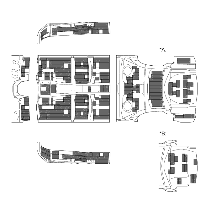
Text in Illustration (2WD and RHD Models) *A Models with Deep Rear Floor Pan *B Models with Shallow Rear Floor Pan Floor Silencer - - 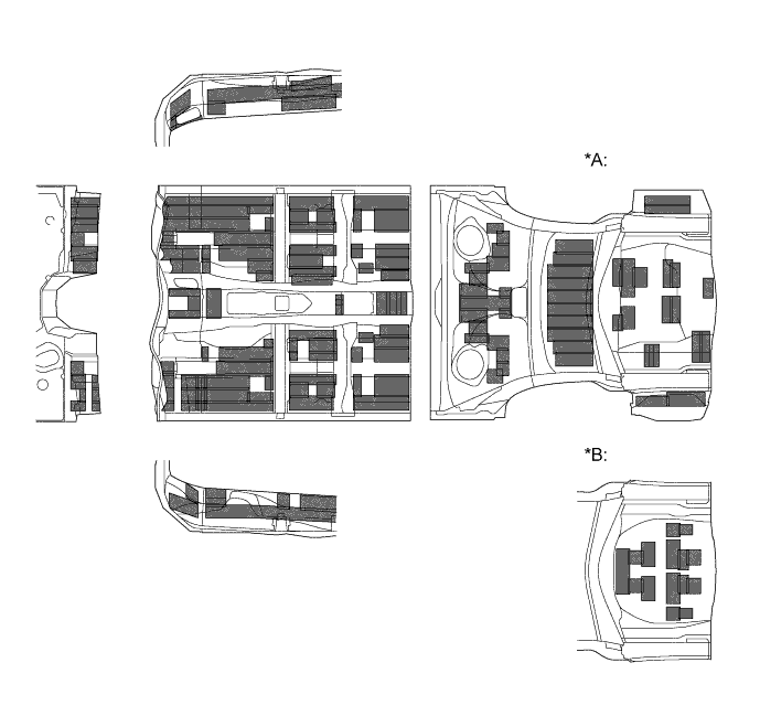
Text in Illustration (AWD and LHD Models) *A Models with Shallow Rear Floor Pan *B Models with Deep Rear Floor Pan Floor Silencer - - -
Sound insulation materials are used in the body frame profile, thus dampening various noises which intrude from the outside of the vehicle to the inside of the cabin.
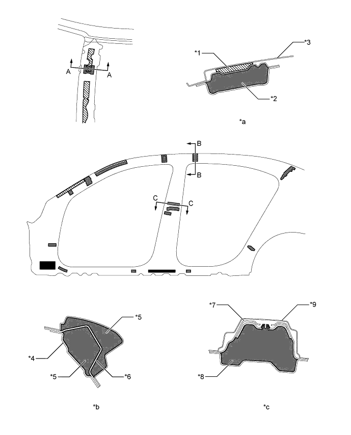
Text in Illustration *1 No. 2 Roof Silencer Pad *2 No. 6 Roof Silencer Pad *3 Roof Panel *4 Inner Roof Side Rail *5 No. 6 Pillar Pad *6 Roof Side Rail *7 Upper Center Body Pillar Reinforcement *8 No. 3 (No. 4) Pillar Pad *9 Outer Side Panel - - *a A - A Cross Section *b B - B Cross Section *c C - C Cross Section - - Damping Materials Sponges Foam Materials - - -
Sound insulation materials are used in the body rocker panel molding assembly, thus dampening various noises which intrude from the outside of the vehicle to the inside of the cabin.
Text in Illustration *1 Body Rocker Panel Molding Assembly - - *a A - A Cross Section *b B - B Cross Section *c C - C Cross Section - - -
All the locations of sound insulation and absorption materials in the cabin and luggage compartment have been optimized, thus creating a quiet drive.
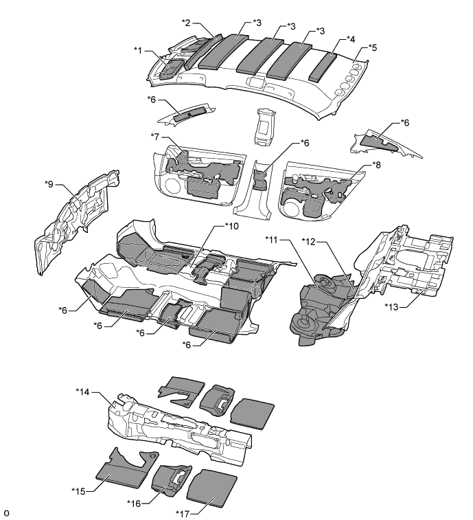
Text in Illustration *1 Visor Assembly *2 No. 1 Roof Silencer Pad *3 No. 2 Roof Silencer Pad *4 No. 4 Roof Silencer Pad *5 Roof Headlining *6 Felt *7 Front Door Silencer Pad *8 Rear Door Silencer Pad *9 Dash Panel Insulator Assembly *10 Front Floor Carpet Assembly Front *11 No. 3 Room Partition Pad *12 No. 2 Room Partition Pad *13 No. 1 Room Partition Pad *14 Front Floor Pad Front *15 Front Floor Silencer Pad *16 Center Floor Silencer Pad *17 Rear Floor Silencer Pad - - 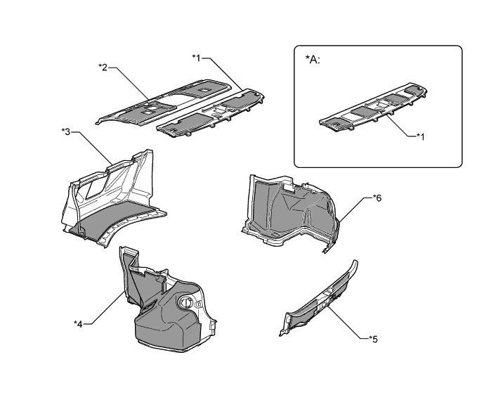
Text in Illustration *A Models with "Mark Levinson" Premium Surround Sound System - - *1 No. 2 Package Tray Trim Panel Assembly *2 Package Tray Trim Panel Assembly *3 Front Luggage Compartment Trim Cover *4 Luggage Compartment Trim Cover Inner LH *5 Rear Floor Finish Plate *6 Luggage Compartment Trim Cover Inner RH Sound Absorption Material - - -
Thinsulate is used for the front door service hole cover and rear door service hole cover as a sound absorbing material, reducing wind noise and road noise entering into the cabin.
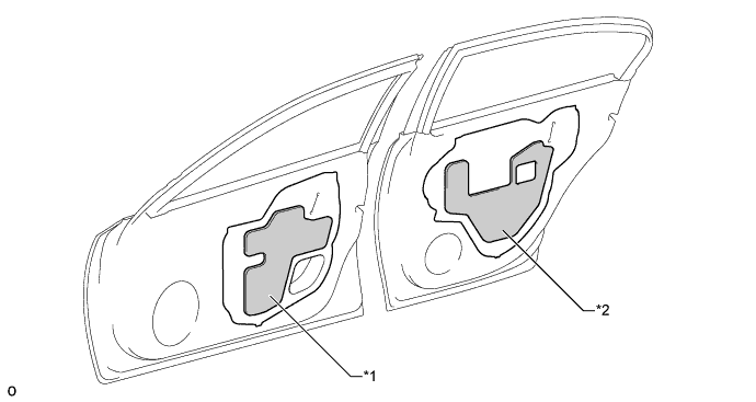
Text in Illustration *1 Front Door Service Hole Cover *2 Rear Door Service Hole Cover -
A gap stuffing structure is given to the first corner portion of the front door weatherstrip, thus suppressing wind noise by blocking airflow.
Text in Illustration *1 Front Door Weatherstrip *2 Side Outer Panel *3 Front Upper Front Door Window Frame - - *a A - A Cross Section *b Gap Stuffing Structure -
By reducing the level differences between the windshield glass and the roof panel, aerodynamic characteristics have been ensured and wind noise has been reduced.
Text in Illustration *1 Windshield Glass *2 Rain Gutter Molding *3 Roof Panel - - *a A - A Cross Section *b Minimal Level Difference between Windshield Glass and Roof Panel Airflow - - -
The differences between the outside windshield molding and windshield glass (C in the illustration), the thickness of the side outer panel (D in the illustration) and the corner shape of the side outer panel (R in the illustration) have been optimized to suppress wind noise.
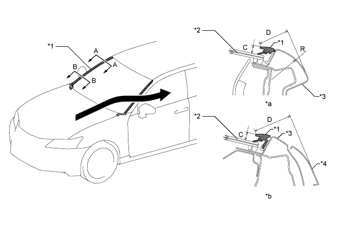
Text in Illustration *1 Outside Windshield Molding *2 Windshield Glass *3 Windshield Glass *4 Side Outer Panel *a A - A Cross Section *b B - B Cross Section Airflow - - -
A front fender side panel protector is provided between the side outer panel and the front fender panel. This prevents road noise from entering the cabin, and achieves superior quietness.
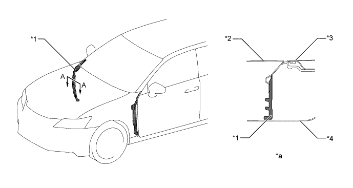
Text in Illustration *1 Front Fender Side Panel Protector *2 Front Fender Panel *3 Outer Front Door Panel *4 Side Outer Panel *a A - A Cross Section - - -
A hood to front fender seal is provided to suppress wind noise on the periphery of the front fender panel and hood sub-assembly.
Text in Illustration *1 Hood to Front Fender Seal *2 Hood Sub-assembly *3 Front Fender Panel - - *a A - A Cross Section - - Airflow - - -
The interval between the front door glass sub-assembly and outer rear view mirror assembly has been optimized to suppress wind noise caused by the wind flowing through the interval.
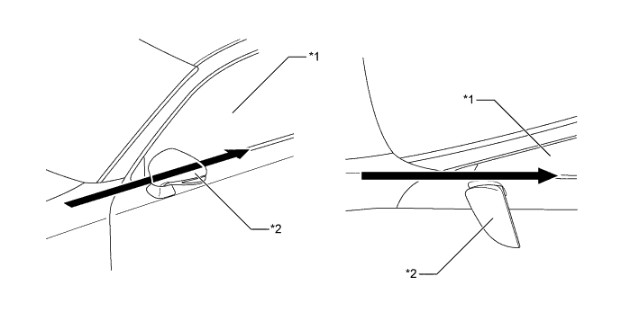
Text in Illustration *1 Front Door Glass Sub-assembly *2 Outer Rear View Mirror Assembly Airflow - - -
Gap-fitting seals (front rear door window frame molding, No. 2 rear door weatherstrip, No. 3 front door weatherstrip, No. 3 rear door weatherstrip) are provided on the periphery of the doors to reduce wind noise and road noise entering into the cabin.
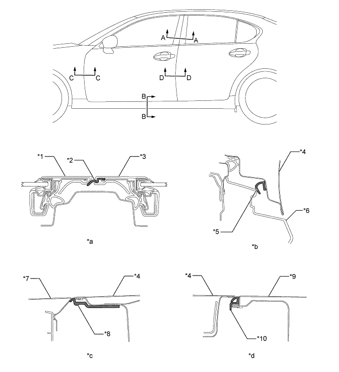
Text in Illustration *1 Rear Front Door Window Frame Molding *2 Weatherstrip *3 Front Rear Door Window Frame Molding *4 Front Door Panel Sub-assembly *5 No. 2 Rear Door Weatherstrip *6 Body Rocker Panel Molding Assembly *7 Front Fender Panel *8 No. 3 Front Door Weatherstrip *9 Rear Door Panel Sub-assembly *10 No. 3 Rear Door Weatherstrip *a A - A Cross Section *b B - B Cross Section *c C - C Cross Section *d D - D Cross Section -
Sponge is added to the inner section of the front door glass weatherstrip inner and rear door glass weatherstrip inner to reduce wind noise and road noise entering into the cabin.
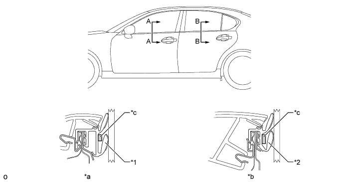
Text in Illustration *1 Front Door Glass Weatherstrip Inner *2 Rear Door Glass Weatherstrip Inner *a A - A Cross Section *b B - B Cross Section *c Sponge - -
-
-